Current of pins on expansion header?
-
I will set up an AC-powered enclosure heater, which will be switched from an SSR. It looks like I need to control from a heater control pin in the expansion header because my bed and two hot ends will occupy the on-board heater FET outputs.
How much current can the expansion pins can sink or source before needing a level shifter or buffer? I just want to make sure I'm not risking the MCU or a pin hooking this up.
-
It depends on the pin
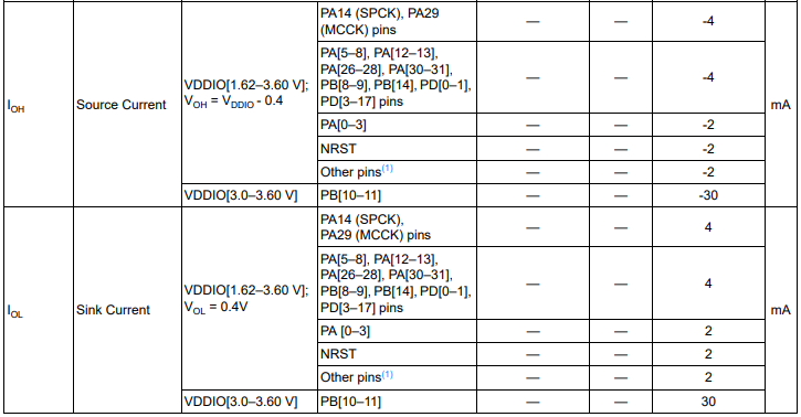
This is the detail from the datasheet:
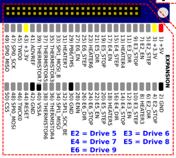
Then to see what pins are mapped to which numbers:
https://duet3d.dozuki.com/Wiki/Duet_2_Pinout_table
and the wiring diagram:
https://duet3d.dozuki.com/Wiki/Duet_Wiring_Diagrams
So for example pin "HEATER3" on the expansion header is pin "PC3" so that can source or sink 2mA maximum
In general you want to use those pins to control a mosfet or similar to then control a load.
-
You should have no problem driving a SSR from the pins on the expansion bus. The heater outputs are active low, so connect the SSR control terminals between the chosen heater output pin and +3.3V.
Duet WiFi hardware designer and firmware engineer
Please do not ask me for Duet support via PM or email, use the forum
http://www.escher3d.com, https://miscsolutions.wordpress.com -
@dc42 said in Current of pins on expansion header?:
You should have no problem driving a SSR from the pins on the expansion bus. The heater outputs are active low, so connect the SSR control terminals between the chosen heater output pin and +3.3V.
I went to the data sheets of a typical Crydom and Schneider SSR and they have input current specs of 5 to 12mA depending on the device. That seems like a lot when some of the µC pins are rated for 2mA.
-
@jrdm, the current depends on the input voltage to the control terminals. The 5 to 12mA current rating is probably measured at some standard voltage such as 10V. The minimum input voltage is usually 3V, so the 3.3V provided by the Duet is only a little above this, and the input current will be low. If you are concerned, connect the SSR input to the output of the Duet as I suggested, and measure the voltage across the control terminals when you command it on. Check that you have at least 3V as required by the SSR datasheet.