Uneven layers
-
@JoergS5 only Z use 10mm belts, Y axis use 2 6mm belts 20t, Z has 24t
-
@Haggan90 I only wanted to give you an idea what could be wrong. I am no physicist to decide where the limit is. This will depend on the tension used also.
I think we misunderstood, with 1 cm I meant the pulley diameter, not the width of the belt.
-
@Haggan90 I have an additional idea: on the image on the right are two pulleys for the Y moves. They are not connected, right? If the Y stucks, one side will brake the movement. E. g. if thermal expansion makes X longer, the linear rails could stuck and lead to unwanted behavior. Did you fix both sides of the X Axis at the Y Axis or only one side (topic: loose and fixed bearing).
I constructed a similar mechanism for Y, but connected the 2 pulleys on the other side with a common shaft, so they cannot rotate differently.
One more thought is the 2:1 slip-sick rule: https://www.machinedesign.com/motion-control/linear-bearings-understanding-21-ratio-and-how-overcome-stick-slip-phenomenon
Maybe something like: you move Z, the LM carriage has preload and changes your overall frame, the distance of the two Y axes change and got stuck, movement is slower/faster than expected, layer is smaller or bigger.
To solve it, Mark Rehorst had an interesting approach: https://drmrehorst.blogspot.com/2018/08/corexy-mechanism-layout-and-belt.html with a moving carriage on one side of the X axis (UMMD image)
-
@JoergS5 very interesting, I will look some more into this!
The Y axis is conected, e.i one side can't move without the other. The Y motor has the shaft going through the stepper. -
@Haggan90 said in Uneven layers:
@droftarts no it's using the same kinematics at the markforge printer.
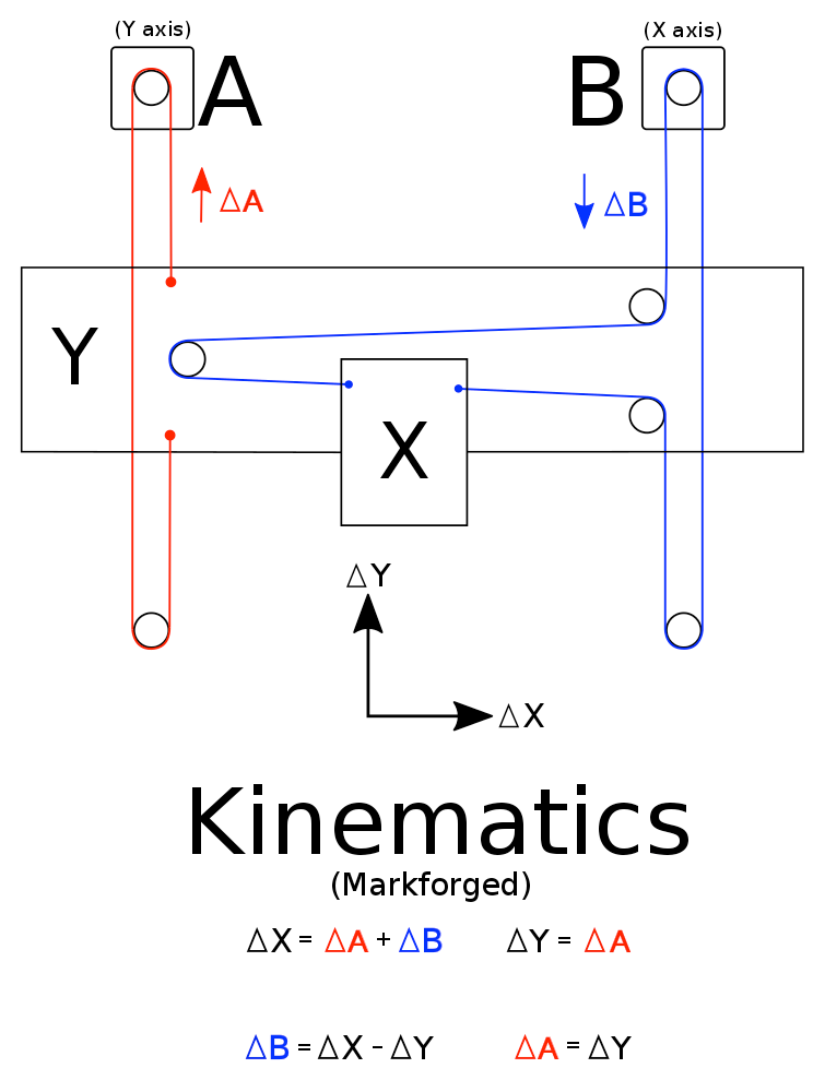
So not a CoreXY, but when you move just one motor (X or Y), the print head moves at 45º? To move the print head along the X axis, both X and Y motor have to turn? So if one axis is loose, the layers will shift at 45º. You've got something loose on one of your axes.
Ian
Bed-slinger - Mini5+ WiFi/1LC | RRP Fisher v1 - D2 WiFi | Polargraph - D2 WiFi | TronXY X5S - 6HC/Roto | CNC router - 6HC | Tractus3D T1250 - D2 Eth
-
@droftarts to move the X axis only the X motor has to turn, but moving Y requires bot X and Y motors to turn.
-
@Haggan90 said in Uneven layers:
@droftarts to move the X axis only the X motor has to turn, but moving Y requires bot X and Y motors to turn.
Yes, I see. But this still means that layers can shift by 45 degrees, as well as 90 degrees, and that either axis could be causing this. But the shift you’re seeing also returns to the original position; it’s limited in its movement. So it HAS to be mechanical slop/backlash, as other effects eg motor settings causing skipped steps would cause more random movement of layers. I’d look at all pulley and belts, which are probably solidly mounted most of the time, except for occasional highest load changes of direction. One way to test this would be to print the same object at half speed.
Ian
-
That is why I suggested to print it rotated by 45° That way you can see which axis is acting up.
-
@OBELIKS this is printed in 45°!

Left printed at 45°, right regular.

-
your white belts are with steel and may be broken.
i agree with JoergS5. if not now you will face problems with those white belts soon because of the 180 degree turn.
-
I'm beginning to think this may have something to do with the fact that I'm using a Volcano hot end, could that be the case here?
-
The strange thing is that this happens at the same height when you compare 45° and normal orientation, so I think it is not the extruder or fillament. It also means it is not X or Y axis.
-
I had some similar Z wobble problems when I updated my Cartesian machine to two independent Z motors. I spent ages looking for bent rods, loose axes, but then it was pointed out that I'd made a massive noob mistake and put M584 Set drive mapping after the motor settings! This causes any axes that don't have accelerations, jerk etc set to use default values, which may work just well enough to fool you into thinking you set it right, and to look for other problems. Do check this! Feel free to post your config.g, too, to see if there's any reason your motor settings on Z may be causing this. Are all your Z motors the same?
As you're running belted Z, the only other thing to check is that none of the pulleys are running eccentrically, which would cause Z banding.
Ian
Bed-slinger - Mini5+ WiFi/1LC | RRP Fisher v1 - D2 WiFi | Polargraph - D2 WiFi | TronXY X5S - 6HC/Roto | CNC router - 6HC | Tractus3D T1250 - D2 Eth
-
i had a problem like this. for me it was ever so slight binding of the z axis. redid the z assembly until in ran without the slightest resistance without the lead screws, then added the lead screws.
-
@droftarts Hi!
I just checked this and I have the M584 before the motor settings
")
what do you mean by "eccentrically"? -
@Veti YEs, I'm beginning to think this might be the problem here.. maybe my Z setup is to contraint.