Endstop for additional axis - coupler for tool changer
-
Maybe this (from wiki) : M584 must come earlier in config.g than any M350 and M906 commands. If it creates new axes, it must also be earlier than any M92, M201, M203, M208, M350, M566, M574 , M667 and M669 commands.
-
That is really interesting and must be an error within the wiki / documentation. I have multiple printers where M584 comes AFTER M667 S1. But I just tried it (moving M584 up, Moving M667 down) and it did not solve the problem.
Thanks for the suggestion!
In addition:
I got these buttons in DWC for the C-Axis (connected to E2 on Duex5). If I use "G92 C0" I can move the axis / coupler in my defined limits between 0 and 4.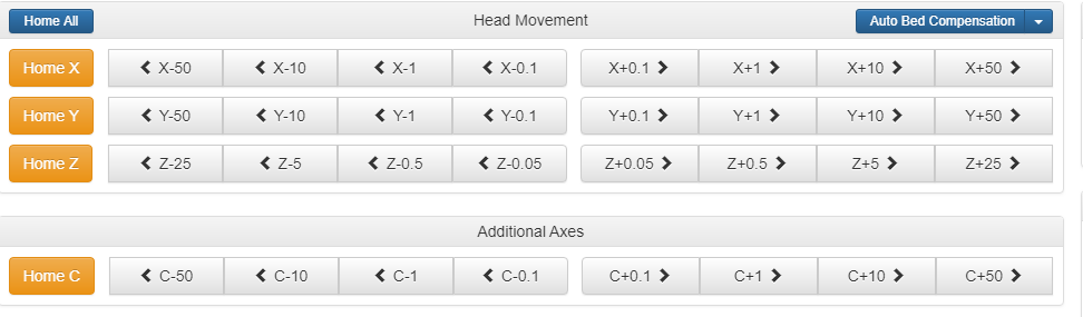
This is really strange. Because DWC shows that these limits are defined for the E0-Drive, not E2. If I half the steps/mm for the C-Axis (2096 instead of 4096) I can see that the coupler moves half the way - so it seems correct. Maybe the display in DWC is just wrong?
But this won't help me....I still can't figure out how to tie the Endstop for C to the C-Axis.
This is my homec.g file - but the coupler does not stop when the endstop is hit. If I hit the endstop manual and look in DWC it flags at E2, not at E0 where all the values seem to be "stored" (see picture).
; homec.g
; called to home the C axis (coupler  for tool changer
;
; generated by MacNite, 2019-10-13

G91               	; relative positioning
G1 S1 C2 F300 	; move quickly to X axis endstop and stop there (first pass)
G1 C1 F1000       	; go back a few mm
G1 S1 C2 F30  	; move slowly to X axis endstop once more (second pass)
G90               	; absolute positioning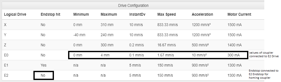
-
One more, probably stupid suggestion : try to change order in M584 command so, that E axis are last ones, like M584 X0 Y1 Z2 C5 E3:4
-
I tried that already - because I looked in the E3D Toolchanger config and it is done there in this way

I also tried renaming the axis to U instead of C...did not help either. -
From my understanding this is why RRF 3.0 was introduced. There you are able to map any endstop pin to s independent axis or not?
-
@smoki3 said in Endstop for additional axis - coupler for tool changer:
From my understanding this is why RRF 3.0 was introduced. There you are able to map any endstop pin to s independent axis or not?
Correct. In RRF2, endstops are allocated to new axes in the order in which you create them. So if the only axis you create is the C axis, it will use the E0 endstop input, regardless of which motor you use to drive it.
Duet WiFi hardware designer and firmware engineer
Please do not ask me for Duet support via PM or email, use the forum
http://www.escher3d.com, https://miscsolutions.wordpress.com -
That is really interesting and annoying at the same time.
So I could Just Setup everything with the C Axis on E0 (Drive + Endstop) and then use E1 to E7 for extruders with Filament Runout.Greets
Max -
@MacNite said in Endstop for additional axis - coupler for tool changer:
That is really interesting and annoying at the same time.
So I could Just Setup everything with the C Axis on E0 (Drive + Endstop) and then use E1 to E7 for extruders with Filament Runout.Greets
MaxYou can connect the C drive motor to whatever output you want, but the C endstop switch must be connected to the E0 endstop input. Filament runout sensors can be connected to any spare endstop inputs (including Z if you use a Z prove to home Z).
-
Yes and no.
This make the setup "functional". But it will not use the wrong display of the Drive Configuration in DWC - Machine properties. The settings (see picture above) show the min, max instandDV etc. linked to E0, while they are in fact linked to drive E2 / C.
To bypass this error within DWC I have to switch my whole setup to use E0 for the C-Axis instead of E2.
Greets
Max -
Update:
I switched the coupler (C-axis) from E2 to E0 (Endstop + Stepper), Extruders are now E1, E2 and so on.It works flawless in this way.