X Axis leaning : need help
-
Everything works fine but the X axis leaning,
1.Checking done with all the mechanical possibilities
2.Slowdown print speed
3. SD card changed
4. Pulse T parameter changed and checked
5      . Motor wire separated from end switch wiringIts a large size machine with X 1700, Y1200 and Z1800, help to find out and solve the issue
X motor : Closed loop Nema23 (2Nm)
Y Motor : Closed loop Nema 34 (12Nm)
Z Motor : closed loop Nema 34 (12Nm)My config.g
; Configuration file for Duet WiFi (firmware version 2.03)
; executed by the firmware on start-up
;
; generated by RepRapFirmware Configuration Tool v2.0.3 on Tue Sep 10 2019 18:28:37 GMT+0530 (IST); General preferences
G90 ; send absolute coordinates...
M83 ; ...but relative extruder moves
M550 P"BIG FACTORY" ; set printer name; Network
M551 P"3m3d" ; set password
M552 S1 ; enable network
M587 S"MMM" P"KINGS1234" ; Configure access point. You can delete this line once connected
M586 P0 S1 ; enable HTTP
M586 P1 S1 ; enable FTP
M586 P2 S1 ; enable Telnet
M584 X5 Y6 Z7 U11 E3:4 ; create the U axis and assign stepper driver 11 to it
; Drives
M569 P5 S1 ; physical drive 5 goes forwards
M569 P6 S0
M569 P5 R1 T3:2.5:5:0 ; physical drive 6 goes forwards
M569 P6 R1 T2.2:2:3:0 ; Physical drive 6 goes forwards
M569 P7 S1 ; physical drive 7 goes forwards
M569 P7 R1 T2.2:2:3:0 ; Physical drive 7 goes forwards
M569 P3 S0 ; physical drive 3 goes forwards
M569 P4 S0 ; physical drive 4 goes forwards
M569 P11 S1
M569 P11 R1 T2.2:2:3:0 ; Physical drive 11 goes forwards
M584 X5 Y6 Z7 U11 E3:4 ; Apply custom drive mapping
M350 X32 Y32 Z32 U32 E32:32 I0 ; Configure microstepping without interpolation
M92 X16 Y334.00 Z8500.00 U25.00 E420.00:420.00 ; Set steps per mm
M566 X1000.00 Y1000.00 Z100.00 U1000.00 E120.00:120.00 ; Set maximum instantaneous speed changes (mm/min)
M203 X7000.00 Y7000.00 Z100.00 U7000.00 E1200.00:1200.00 ; Set maximum speeds (mm/min)
M201 X500.00 Y500.00 Z100.00 U500.00 E250.00:250.00 ; Set accelerations (mm/s^2)
M906 X800.00 Y800.00 Z800.00 U800.00 E800.00:800.00 I30 ; Set motor currents (mA) and motor idle factor in per cent
M84 S30 ; Set idle timeout; Axis Limits
M208 X1600 Y1100 U1600 Z1700 ; Set axis maxima
M208 X-50 Y0 U0 Z-0.2 S1 ; Set axis minimum (adjust to make X=0 and Y=0 the edge of the bed); Endstops
M574 X1 Y1 Z0 U2 S1 ; Set endstop configuration (X and Y endstops at low end, U endstop at high end, active high, no Z endstop)
; Z-Probe
M574 Z1 S2 ; set endstops controlled by probe
M307 H7 A-1 C-1 D-1 ; disable heater on PWM channel for BLTouch
M558 P5 H5 F120 T6000 I1 ; set Z probe type to bltouch and the dive height + speeds
G31 P500 X0 Y0 Z1.55 ; set Z probe trigger value, offset and trigger height
M557 X20:1500 Y20:1000 S300 ; define mesh grid; Heaters
;M141 H4 ; assign chamber heater to heater 0
M305 P0 T100000 B4138 R4700 ; set thermistor + ADC parameters for heater 0
M143 H0 S120 ; set temperature limit for heater 0 to 120C
M305 P1 X200 ; configure PT100 for heater 1
M143 H1 S500 ; set temperature limit for heater 1 to 500C
M305 P2 X201 ; configure PT100 for heater 2
M143 H2 S500 ; set temperature limit for heater 2 to 500C
M305 P4 X202 ; configure PT100 for heater 4
;M143 H4 S120 ; set temperature limit for heater 4 to 120C; Fans
M106 P0 S0 I0 F500 H T45 ; Set fan 0 value, PWM signal inversion and frequency. Thermostatic control is turned on
M106 P1 S1 I0 F500 H1 T45 ; Set fan 1 value, PWM signal inversion and frequency. Thermostatic control is turned on
M106 P2 S1 I0 F500 H2 T45 ; Set fan 2 value, PWM signal inversion and frequency. Thermostatic control is turned on
; Tools
M563 P0 S"FIRST" D0 H1 F0 ; Define tool 0
G10 P0 X0 Y0 Z0 ; Set tool 0 axis offsets
G10 P0 R0 S0 ; Set initial tool 0 active and standby temperatures to 0C
M563 P1 S"SECOND" D1 H2 X3 F2 ; Define tool 1
G10 P1 Y0 U0 Z0 S0 R0 ; set tool 1 offsets and temperatures
M563 P2 S"MIXED" D0:1 H1:2 X0:3 F0:2 ; tool 2 uses both extruders, hot end heaters and fans, and maps X to both X and UG10 P2 X0 Y0 Z0 ; Set tool 2 axis offsets
G10 P2 X500 Y0 U-500 S0 R0 ; set tool offsets and temperatures
M567 P2 E1:1 ; set mix ratio 100% on both extruders; Automatic power saving
M911 S10 R11 P"M913 X0 Y0 G91 M83 G1 Z3 E-5 F1000" ; Set voltage thresholds and actions to run on power loss; Custom settings are not configured
; Miscellaneous
M501 ; Load saved parameters from non-volatile memory -
Hi,
What do you mean by "X Axis leaning"?
Thanks.
Frederick
-
the pictures did not upload
-
(yeah i find if trying to edit the post while uploading it can break the image tag. best to wait for upload to finish i recon)
-
@Milan said in X Axis leaning : need help:
M569 P5 R1 T3:2.5:5:0 ; physical drive 6 goes forwards
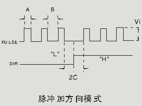
In my experience, if the print is leaning with external drivers it's often due to setup and hold times for the DIR signal. Try extending these timings significantly and see if it improves. If it does, start reducing it down to a reasonable value.
Another thing that can cause it is loose pulleys/couplers connecting to the motor.
-
@Milan Pozdrav,
I assume that "leaning axis" will be explained when the images are uploaded :).Few questions, your config is for duet2wifi, are you using duet2wifi or some other board? What drivers are you using? On-board TMC drivers on duet2wifi or some other "on-board" drivers or some external drivers? If external drivers, which ones? I had an issue with TB6560 drivers for e.g. where I had skipped step every time I change direction. The problem was that attm no reprap firmware knew how to generate steps that conform to TB requirements.
Now, you should check your driver manual, but if you are using the on-board drivers on duet2wifi this should already be handled in the firmware.
-
Thank you so much, uploading the pics ,

!
-
@smece X and U axis are connected with these External drivers...
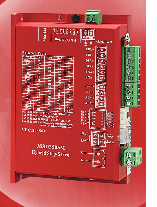
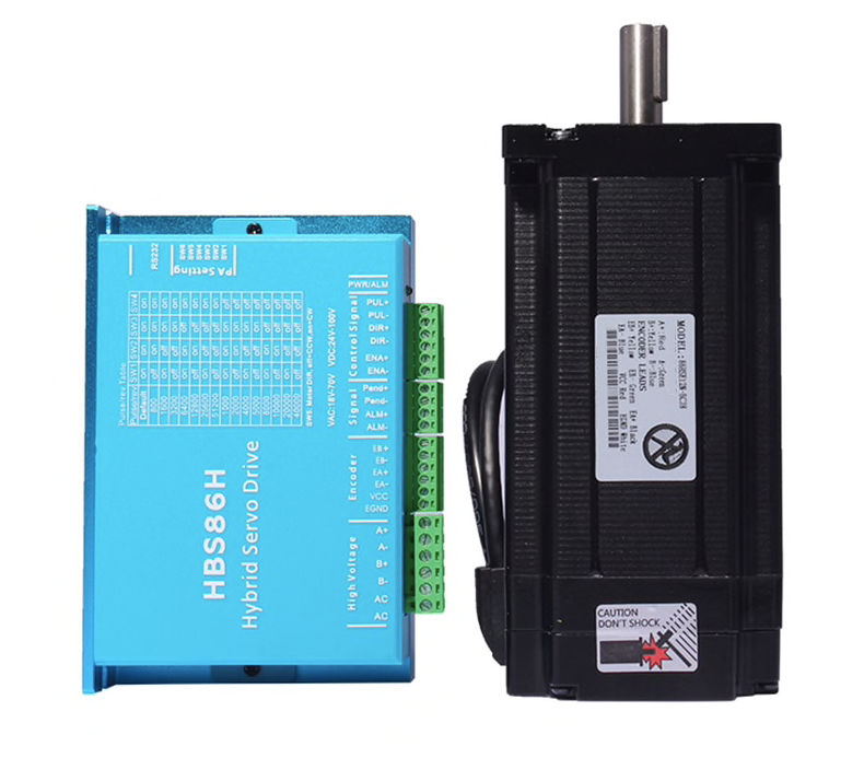
Y and Z axis are connected with the below ones...
-
I (unfortunately) have very little experience with these closed circuit drivers; I have one HBS57 with matching motor sitting under my desk keeping dust for me to try it out but from what I remember if they skip step the alarm should go on. Do you have anything linked to the alarm output?
Now the Y is not a problem, but Y uses HBS 8A driver (these are the original leadshine PRC ones or bulgarian Vallder?) , not the JSSD 5A one that's on X; can you swap X and Y drivers to test if that's maybe the problem? have you tried lower acceleration settings for X axis?
in any way, first thing would be to attach something to the ALARM output to see if you are losing steps
-
The usual cause of this problem when using external drivers is that you have set the step-to-direction hold time too low. This is the last of the 4 values in the T parameter of the M569 commands. Looks like you have them all set to zero.
-
Alarm yet to connect, no step skipping , it just moving a bit to (left side) X- while changing every layer
I don't know why it changing the track (before it reaching the length it supposed reach on X+) while only changing the layers, otherwise X travels full length for any layer -
@dc42 , Thanks David, I've changed other 3 values and checked, except the 4th one, will increase and check the same
-
Thankyou , Its working fine now ...after changing the parameter of the M569