monitoring mesh bed compensation level
-
If you preheat the bed, the B1 parameter will only disable the heater for the probe move portion and resume heating after. It should be able to maintain close to the set temp.
-
Oh, ok ... I will leave it as is for now and see how it works out. This is going to take some time
")
I normally run with a 441 point mesh bed when everything is working as it should. Based on the speed so far, it will take the better part of two hours to do the full run !
Just finished the first 100 point scan, 2 more to go! -
@jens55 that seems like overkill for a mesh sequence. When set up, the BL should be able to generate a stable mesh with far less. If we take a Prusa for instance - even on the 9 x 9 set up from a factory configuration takes less than a minute (albeit a different style of sensor).
Is there a specific reason you're running such a dense mesh probe area? If there is a single probe with magnetic interference in the hour of probing (without safeguards like Phaedrux has mentioned) it will show up as a high or low point on your heat map and the entire mesh run is useless, the printer will use what data it is given so an extreme outlier created by an incorrect probe will mean the printer will compensate accordingly.
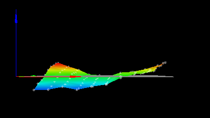
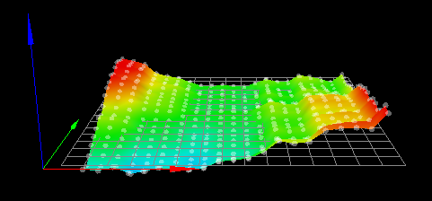
Do you have a screen shot of your terrain or heat map?
A method I tend to use when I set up new printers is to start with less probe points and add more as you build a solid foundation map.
If you start with, say 4-8 points in total and get the deviation low, then 8-12 and get it low again etc etc you will save lots of time and remove the almost certain introduction of error in a 441 point scan. -
I run a 500 * 500 bed so I find the more data points the better. I too start out with 4 points and go up from there
I now have 2 height maps with the new settings and multi probing. The difference between data points is down to a maximum of about 0.03 mm so that is an improvement.
-
The new parameters for the BLTouch help. I will see how it works out in real life with a 441 point mesh map and gauging the gap between the bed and the nozzle.
Here are 4 runs of 10 probes. Again, no x/y movement between the 10 data points but full z home between the 4 separate sets of data points.
-0.054 -0.055 -0.051 -0.053 -0.051 -0.053 -0.053 -0.050 -0.050 -0.049, mean -0.052, deviation from mean 0.002
-0.047 -0.047 -0.043 -0.045 -0.043 -0.043 -0.043 -0.043 -0.042 -0.040, mean -0.043, deviation from mean 0.002
-0.048 -0.050 -0.048 -0.044 -0.044 -0.044 -0.045 -0.043 -0.042 -0.040, mean -0.045, deviation from mean 0.003
0.045 -0.044 -0.044 -0.042 -0.043 -0.039 -0.035 -0.035 -0.033 -0.031, mean -0.039, deviation from mean 0.005Note that these figures are better than the differences seen between the mesh maps.
-
The results are in and I am not impressed. Checking the first row that was probed, there is a difference of bed to nozzle distance of 0.25 mm from one side to the next (with mesh correction active!). The previous version with a faster and single probing showed approximate;y 0.35 mm difference between one side and the other so it is an improvement but it literally took 2:00 hours to run the scan.
I am expecting the nozzle to bed difference to be a maximum of 0.05 between any points on the bed but would prefer 0.002 mm. In any case, I am a long way from a satisfactory mesh bed scan
heightmap(3).csv -
Do you have any taper configured?
-
Yes, the bed equalization tapers out at 10 mm as suggested in the docs.
I have printed a large 3 line wide test strip over a good portion of the bed (1 mm line width for a total of 3 mm total width) at 0.2 mm height. The resulting strip was between 0.15 and 0.25 mm in height. It is not ideal and not what I was hoping for but I think I can work with that result. I was hoping to be able to use 0.1 mm for the first layer but will just have to limit myself to 0.2 mm thickness for the first layer. The 0.2 mm for the first layer is my choice for the majority of all prints anyway.
Mini poll: On larger prints, let's say 200 to 400mm along one direction, what kind of deviation in print height do you see over that distance? I routinely measure my skirt from my prints at many spots and this is what I am referring to with this question. In the above example the deviation is +- 0.05 mm.
I am doing the mini poll to see if my results are typical or if I should expect better.
If you are doing substantially better, please state over what distance the deviation was measured and what printer you are using. I am using the mechanics of a CR10 S5 so a low end printer and I would think that a much higher price point gets you more precision (or does it ?) -
Disable taper and see if it makes a difference. I think it might.
-
Could you explain why you think that disabling the taper might improve the end result ? Remember that I am only measuring the first layer in my experiments so taper should not even be in the equation ....
-
I speculate that taper is already being applied on your first layer, hence why you're seeing less adjustment than expected.
-
Thanks, I will give it a try!
-
I am having a hard time recreating the conditions of my last test after disabling the taper. The results I got were not as good as in the previous test but that is probably more a reflection on my abilities rather than any difference in the mesh leveling system.
I think it would help if it was possible to track the amount of correction applied as the printer does it's thing but I gather by the lack of response to my question about this that it is not possible to do so.
Unless other people tell me that they are getting much better results with mesh bed compensation, I will assume that I am at the limit of what this particular printer can do.
I have had about 9 months screwing around with a piezo probe so I might as well spend the next 9 months messing about with the BLTouch .....Thanks for all the suggestions and help !
-
@jens55 said in monitoring mesh bed compensation level:
The results are in and I am not impressed. Checking the first row that was probed, there is a difference of bed to nozzle distance of 0.25 mm from one side to the next (with mesh correction active!).
Some possible explanations:
- Your print head may be tilting as it moves from one side to the other, and because your BLTouch is offset from the nozzle, this changes the relative heights of the BLTouch and the nozzle
- You are probing with bed heat on, and different magnetic fields from different sides of the bed are changing the BLTouch trigger height. Use the M558 B parameter to turn off heaters during probing moves.