IR sensor and glass surface
-
Hey all!
I am getting some pretty bad readings on my ultrabase print bed with my newly installed IR sensor but im determined to use glass with no adhesives as my print surface. Does anyone have a bullet proof easy way to get the IR sensor working well with glass?
So far I've seen using black vinyl underneath the glass or painting it.
For black vinyl am I thinking correctly that you are still adhering it to the underside of the glass? Or would you be adding it onto your heated bed at that point which a glass sheet would sit on?I'm using this with Marlin 2.0 and pretty certain its my print surface which is messing things up. Could I print with the lights off to rule out ambient light issues?
Here are results of standard deviation tests which I feel look very very good:
Recv: 10 of 10: z: -0.027
Recv: Finished!
Recv: Mean: -0.030146 Min: -0.035 Max: -0.026 Range: 0.009
Recv: Standard Deviation: 0.002663At a different spot
Recv: 10 of 10: z: -0.027
Recv: Finished!
Recv: Mean: -0.030146 Min: -0.035 Max: -0.026 Range: 0.009
Recv: Standard Deviation: 0.002663
Recv:A very bad G29 attempt
Recv: 0 1 2
Recv: 0 -0.074 -0.001 +0.438
Recv: 1 -0.039 -0.107 +2.553
Recv: 2 +0.025 +0.031 -0.245
Recv:Thanks!
-
@singhm29 said in IR sensor and glass surface:
Hey all!
I am getting some pretty bad readings on my ultrabase print bed with my newly installed IR sensor but im determined to use glass with no adhesives as my print surface. Does anyone have a bullet proof easy way to get the IR sensor working well with glass?
So far I've seen using black vinyl underneath the glass or painting it.
For black vinyl am I thinking correctly that you are still adhering it to the underside of the glass? Or would you be adding it onto your heated bed at that point which a glass sheet would sit on?The approaches that have worked well for me are matt black paper underneath the glass, and painting the underside with matt black paint. Is your black vinyl shiny? It must be a matt black surface. Don't use any adhesive to glue it to the glass, because the adhesive won't be black.
I'm using this with Marlin 2.0 and pretty certain its my print surface which is messing things up. Could I print with the lights off to rule out ambient light issues?
The only ambient light that affects the IR sensor is very bright sunlight (no clouds in front of the sun) reflecting directly off the glass into the sensor. When the sensor detects this, it blinks the LED rapidly to tell you.
Here are results of standard deviation tests which I feel look very very good:
Recv: 10 of 10: z: -0.027
Recv: Finished!
Recv: Mean: -0.030146 Min: -0.035 Max: -0.026 Range: 0.009
Recv: Standard Deviation: 0.002663At a different spot
Recv: 10 of 10: z: -0.027
Recv: Finished!
Recv: Mean: -0.030146 Min: -0.035 Max: -0.026 Range: 0.009
Recv: Standard Deviation: 0.002663
Recv:Yes those look good - the range is low and the trigger height is consistent. When the probe triggers, the bottom edge of the sensor should be between 2.5mm and 3.5mm above the glass. Is it?
A very bad G29 attempt
Recv: 0 1 2
Recv: 0 -0.074 -0.001 +0.438
Recv: 1 -0.039 -0.107 +2.553
Recv: 2 +0.025 +0.031 -0.245
Recv:I am not familiar with the Marlin G29 report. What do those figures mean: is it a 3x3 grid of measured deviations?
Please confirm that the top of the glass is clean and not coated with anything.
-
"The approaches that have worked well for me are matt black paper underneath the glass, and painting the underside with matt black paint. Is your black vinyl shiny? It must be a matt black surface. Don't use any adhesive to glue it to the glass, because the adhesive won't be black."
Currently have not put anything underneath the ultrabase as users have said it works with it. Right so it sounds like if I go the vinyl route make sure the non adhesive side has a matte finish and stick the adhesive side to the heated bed
"The only ambient light that affects the IR sensor is very bright sunlight (no clouds in front of the sun) reflecting directly off the glass into the sensor. When the sensor detects this, it blinks the LED rapidly to tell you."
Great I'm not seeing any of that and I have a 1.3 board from an official reseller if that makes a difference.
"Yes those look good - the range is low and the trigger height is consistent. When the probe triggers, the bottom edge of the sensor should be between 2.5mm and 3.5mm above the glass. Is it?"
Actually this is where things are a bit confusing..I moved my Z axis down until it caught a sheet of paper. I set this as my Z zero position (G92 Z0) from here I moved up until the IR sensor LED turned on which was only 0.4mm from the print surface. The glass is clean, I never use adhesives as I find it great to print straight on glass and have the auto release when it cools down.
"A very bad G29 attempt
Recv: 0 1 2
Recv: 0 -0.074 -0.001 +0.438
Recv: 1 -0.039 -0.107 +2.553
Recv: 2 +0.025 +0.031 -0.245
Recv:
I am not familiar with the Marlin G29 report. What do those figures mean: is it a 3x3 grid of measured deviations?"This is a 3x3 probing of the bed with 3 probes at each point which would be used for bed leveling compensation.
-
The figures in the right hand column of the 3x3 grid are very bad. Are you certain that the sensor is still over the bed when these points are probed?
Duet WiFi hardware designer and firmware engineer
Please do not ask me for Duet support via PM or email, use the forum
http://www.escher3d.com, https://miscsolutions.wordpress.com -
@dc42 said in IR sensor and glass surface:
The figures in the right hand column of the 3x3 grid are very bad. Are you certain that the sensor is still over the bed when these points are probed?
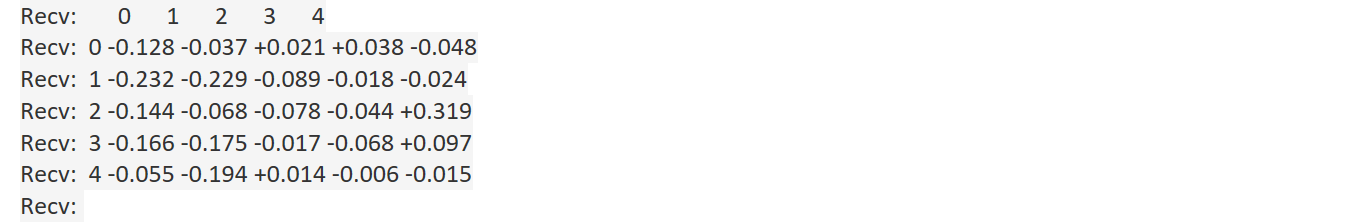
I suspected that as well and changed my bed size, probing amount to 5 per point and used a 5x5 grid instead results seem better with a few points however being very off. Not sure if I should chalk those up to the probing occuring at points where there might be bad reflection or something messing with the sensor readings.
-
It's hard for me to say without a visual representation of the bed map (which for Marlin I think you need Octoprint and plugin to get), however I think that map is fairly smooth with the exception of that +0.319 figure at the middle right. I suggest you look into why that one is so different from the others. The one below it is rather high too.