Duet3D Logo Duet3D
    • Tags
    • Documentation
    • Order
    • Register
    • Login
    1. Home
    2. singhm29
    • Profile
    • Following 0
    • Followers 0
    • Topics 19
    • Posts 72
    • Best 2
    • Controversial 0
    • Groups 0

    singhm29

    @singhm29

    2
    Reputation
    3
    Profile views
    72
    Posts
    0
    Followers
    0
    Following
    Joined Last Online

    singhm29 Unfollow Follow

    Best posts made by singhm29

    • RE: Very confused with Duet mesh level correction

      @phaedrux

      I wasn't too sure if it was the gantry or the bed so I tried correcting both.

      Here was my bed level before doing any changes to the physical bed.
      29a932e6-7d75-452d-b2ff-d78d87b9f857-image.png

      Here it was after I loosened the bed corners so that the springs were all completely loose and then I moved the gantry to rest on the steppers at the bottom of the Z axis (equalizing the Z gantry tilt from left to right and back to front). From here again I set the Z probe offset which changed from 2.5 to 3.1mm. Here is what I got from that
      e154ef0c-974d-4bb6-b968-a08e12dde664-image.png

      Not particularly promising...so being humble I decided to give another go at bed leveling manually. Here is the result from that 3dfb185b-0687-45f1-9f7e-da333b3f6267-image.png

      Now to give some context I am not new to bed leveling manually as I have been printing since 2015 but here what was really baffling.

      I turned off G29, G32 and G29 S1 from my start gcode printed for a round and the first layer came out well.

      I turned on G29 and G32 and lo and behold with no physical changes to the bed I now had this
      969467e5-1ed4-4980-960b-a2f02dcc4ecb-image.png

      Thinking it was possibly the presence of G29 followed by G29 S1 I turned it back on to see if that would cause an issue. Again the new bed level came out great.
      a3911065-92a1-4739-91b2-aa9cbc834871-image.png

      So I am back to a good looking bed but I have no idea how it was fixed. I'm hoping this will stick and wont be doing any physical changes. Lets see how long this lasts! Open to any thoughts but either way appreciate walking me through the possible issues.

      posted in Tuning and tweaking
      singhm29undefined
      singhm29
    • RE: Skipping gridpoint during probing despite offset inclusion

      @fcwilt Hey thank you very much for your feedback as well I went ahead and tried what you advised above and it worked very well! Makes alot of sense to use that approach to keep things simple and I am now happy to report all points are probed and it gets quite close to the edge on each side still.

      I used @jay_s_uk tip on changing my probe point to X35 and that also fixed my ramming of my X endstop when executing G32.

      Thank you for the help, looks like probing is figured out for now!

      posted in Tuning and tweaking
      singhm29undefined
      singhm29

    Latest posts made by singhm29

    • RE: Skipping gridpoint during probing despite offset inclusion

      @fcwilt Hey thank you very much for your feedback as well I went ahead and tried what you advised above and it worked very well! Makes alot of sense to use that approach to keep things simple and I am now happy to report all points are probed and it gets quite close to the edge on each side still.

      I used @jay_s_uk tip on changing my probe point to X35 and that also fixed my ramming of my X endstop when executing G32.

      Thank you for the help, looks like probing is figured out for now!

      posted in Tuning and tweaking
      singhm29undefined
      singhm29
    • RE: Skipping gridpoint during probing despite offset inclusion

      @jay_s_uk Thanks for the thoughts I will test this out but what I fear here is that if I change M208 to M208 X-31:609 Y-3:611 Z0:578.5 is that this may fix the probing but when I home X it will think that when it hits home its -31 which would be wrong. Interesting regarding the lead screw and I will try that out as well.

      posted in Tuning and tweaking
      singhm29undefined
      singhm29
    • Skipping gridpoint during probing despite offset inclusion

      Howdy all,

      Switched out my hotend/extruder and had another go at fixing issues I've always had with my mesh probing.

      Essentially my mesh does not probe an entire column saying that it cannot reach the location despite actually being able to.

      M208 Axis limits X0.0:609.0, Y-3.0:611.0, Z0.0:578.5
      M557 Grid: X-31.0:594.0, Y3.0:562.0, radius -1.0, X spacing 156.2, Y spacing 139.8, 25 points
      G31 Z probe 0: current reading 1000, threshold 25, trigger height 2.850, offsets X31.0 Y-44.0
      

      After reading previous posts I tried including my probe offsets to no avail it still misses an entire row closest to X0, basically any point with an X coordinate of 0 will be skipped. I have tried increasing my axis limit to be -31 without a change, I have tried with it as 0 for the M557 grid.

      To add to this oddity if I run G32 it for some reason overshoots my X0 point and tries going past my endstop for a bit before stopping and probing, the second pass it has no issue stopping at X0 and running correctly.

      Any thoughts would be much appreciated.

      ; bed.g
      ; called to perform automatic bed compensation via G32
      ;
      ; generated by RepRapFirmware Configuration Tool v3.2.3 on Mon Mar 15 2021 19:09:36 GMT+0100 (Mitteleuropäische Normalzeit)
      M561                                                       ; Clear any existing bed transform.
      G28 ; home
      G1 X300 Y300 F4000 ; go to center of bed this isnt in his
      ;G1 Z220 F10000 took this out since we dont wanna raise
      ;M558 F10000
      G30
      
      ; first pass
      G30 P0 X0 Y300 Z-99999 ; probe near a leadscrew, half way along Y axis
      G30 P1 X560 Y300 Z-99999 S2 ; probe near a leadscrew and calibrate 2 motors
      ; second pass
      G30 P0 X0 Y300 Z-99999 ; probe near a leadscrew, half way along Y axis
      G30 P1 X560 Y300 Z-99999 S2 ; probe near a leadscrew and calibrate 2 motors
      
      ;G1 X10 Y210 Z10 F10000
      
      posted in Tuning and tweaking
      singhm29undefined
      singhm29
    • RE: Very confused with Duet mesh level correction

      @phaedrux

      I wasn't too sure if it was the gantry or the bed so I tried correcting both.

      Here was my bed level before doing any changes to the physical bed.
      29a932e6-7d75-452d-b2ff-d78d87b9f857-image.png

      Here it was after I loosened the bed corners so that the springs were all completely loose and then I moved the gantry to rest on the steppers at the bottom of the Z axis (equalizing the Z gantry tilt from left to right and back to front). From here again I set the Z probe offset which changed from 2.5 to 3.1mm. Here is what I got from that
      e154ef0c-974d-4bb6-b968-a08e12dde664-image.png

      Not particularly promising...so being humble I decided to give another go at bed leveling manually. Here is the result from that 3dfb185b-0687-45f1-9f7e-da333b3f6267-image.png

      Now to give some context I am not new to bed leveling manually as I have been printing since 2015 but here what was really baffling.

      I turned off G29, G32 and G29 S1 from my start gcode printed for a round and the first layer came out well.

      I turned on G29 and G32 and lo and behold with no physical changes to the bed I now had this
      969467e5-1ed4-4980-960b-a2f02dcc4ecb-image.png

      Thinking it was possibly the presence of G29 followed by G29 S1 I turned it back on to see if that would cause an issue. Again the new bed level came out great.
      a3911065-92a1-4739-91b2-aa9cbc834871-image.png

      So I am back to a good looking bed but I have no idea how it was fixed. I'm hoping this will stick and wont be doing any physical changes. Lets see how long this lasts! Open to any thoughts but either way appreciate walking me through the possible issues.

      posted in Tuning and tweaking
      singhm29undefined
      singhm29
    • RE: Very confused with Duet mesh level correction

      Thanks for the feedback. All changes were made other than changing any hardware yet.

      Confirmed movement
      5fff8344-2aa0-4c15-860f-8f8aaaf03172-image.png

      Result from G29 without running G32
      8958e7a3-8fc5-465f-bdbd-b4b867f96e99-image.png

      Result from G32 followed by G29
      9439c5b7-b7ee-4ecb-b921-ee9799240f0f-image.png

      Other interesting things I observed
      -when running G29 it skips the first row because the Bltouch would end up trying to probe off the bed
      9d102a2c-67c4-4ffe-8da0-f2cef88bd8e6-image.png

      -after this I homed to center and again set to Z=0, the distance was no longer 1 paper sheet but a much larger distance

      In terms of bed tilt along the Y axis I'm trying to imagine how I would correct that, normally if I have a bad nozzle crash I will move down the Z axis to the lowest point turn off stepper motors and then manually move down until my bed rests on both Z axis stepper motors to equal out both sides. I feel like that would correct X axis skew and help Y axis but im not sure after that what I could change...I guess I could also verify that there is actually tilt occuring by manually leveling the bed and turning off any compensation and seeing if jogging the Z axis up and down results in a change of Z distance between the front and back?

      posted in Tuning and tweaking
      singhm29undefined
      singhm29
    • RE: Very confused with Duet mesh level correction

      @o_lampe

      Yea I figured that this could just be a minor setting I mixed up when I set things up however I did use the configurator as my base to get me started. I would not be surprised if I fudged something in that process, ive become to used to Marlin but love the hardware Duet offers just wish I could get my head around the firmware.

      Its a cartesian frame where the bed drops down as the print progresses
      7167e6a2-fdea-46c3-81aa-8eaad3bb7bbb-image.png

      X axis endstop is on the print head and homes to the minimum

      Y axis endstop is in the back left corner and homes to a maximum

      Z axis endstop is the BLtouch which homes to a minumum

      posted in Tuning and tweaking
      singhm29undefined
      singhm29
    • RE: Very confused with Duet mesh level correction

      @Phaedrux

      Not a problem
      M122

      M122
      === Diagnostics ===
      RepRapFirmware for Duet 3 MB6HC version 3.2 running on Duet 3 MB6HC v0.6 or 1.0 (standalone mode)
      Board ID: 08DJM-956L2-G43S4-6JKDD-3SJ6T-TB6GH
      Used output buffers: 1 of 40 (36 max)
      === RTOS ===
      Static ram: 149788
      Dynamic ram: 93192 of which 132 recycled
      Never used RAM 115720, free system stack 122 words
      Tasks: NETWORK(ready,171) ETHERNET(blocked,109) HEAT(blocked,271) CanReceiv(blocked,927) CanSender(blocked,350) CanClock(blocked,349) TMC(blocked,19) MAIN(running,671) IDLE(ready,19)
      Owned mutexes:
      === Platform ===
      Last reset 84:30:27 ago, cause: software
      Last software reset at 2021-03-19 23:20, reason: User, GCodes spinning, available RAM 115720, slot 0
      Software reset code 0x0003 HFSR 0x00000000 CFSR 0x00000000 ICSR 0x00400000 BFAR 0x00000000 SP 0x00000000 Task MAIN Freestk 0 n/a
      Error status: 0x00
      Aux0 errors 0,0,0
      Aux1 errors 0,0,0
      MCU temperature: min 39.6, current 40.5, max 44.5
      Supply voltage: min 22.9, current 23.9, max 24.6, under voltage events: 0, over voltage events: 0, power good: yes
      12V rail voltage: min 12.1, current 12.2, max 12.3, under voltage events: 0
      Driver 0: position 30073, standstill, reads 53715, writes 130 timeouts 0, SG min/max 0/915
      Driver 1: position 35556, standstill, reads 53715, writes 130 timeouts 0, SG min/max 0/125
      Driver 2: position 365607, standstill, reads 53705, writes 140 timeouts 0, SG min/max 0/1023
      Driver 3: position 0, standstill, reads 53796, writes 50 timeouts 0, SG min/max 0/198
      Driver 4: position 0, standstill, reads 53706, writes 140 timeouts 0, SG min/max 0/1023
      Driver 5: position 0, standstill, reads 53835, writes 11 timeouts 0, SG min/max 0/0
      Date/time: 2021-03-23 11:50:47
      Slowest loop: 69.48ms; fastest: 0.03ms
      === Storage ===
      Free file entries: 10
      SD card 0 detected, interface speed: 25.0MBytes/sec
      SD card longest read time 3.3ms, write time 22.6ms, max retries 0
      === Move ===
      DMs created 125, maxWait 416792ms, bed compensation in use: mesh, comp offset 0.000
      === MainDDARing ===
      Scheduled moves 3200, completed moves 3200, hiccups 0, stepErrors 0, LaErrors 0, Underruns [0, 0, 33], CDDA state -1
      === AuxDDARing ===
      Scheduled moves 0, completed moves 0, hiccups 0, stepErrors 0, LaErrors 0, Underruns [0, 0, 0], CDDA state -1
      === Heat ===
      Bed heaters = 0 -1 -1 -1 -1 -1 -1 -1 -1 -1 -1 -1, chamberHeaters = -1 -1 -1 -1
      Heater 0 is on, I-accum = 0.0
      Heater 1 is on, I-accum = 0.6
      === GCodes ===
      Segments left: 0
      Movement lock held by null
      HTTP is idle in state(s) 0
      Telnet is idle in state(s) 0
      File is idle in state(s) 0
      USB is idle in state(s) 0
      Aux is idle in state(s) 0
      Trigger is idle in state(s) 0
      Queue is idle in state(s) 0
      LCD is idle in state(s) 0
      SBC is idle in state(s) 0
      Daemon is idle in state(s) 0
      Aux2 is idle in state(s) 0
      Autopause is idle in state(s) 0
      Code queue is empty.
      === Network ===
      Slowest loop: 67.65ms; fastest: 0.02ms
      Responder states: HTTP(0) HTTP(0) HTTP(0) HTTP(0) HTTP(0) HTTP(0) FTP(0) Telnet(0), 0 sessions Telnet(0), 0 sessions
      HTTP sessions: 1 of 8
      - Ethernet -
      State: active
      Error counts: 0 0 1 0 0
      Socket states: 5 2 2 2 2 0 0 0
      === CAN ===
      Messages queued 1217061, send timeouts 2738195, received 0, lost 0, longest wait 0ms for reply type 0, free buffers 48
      

      M98 P"config.g"

      M98 P"config.g"
      HTTP is enabled on port 80
      FTP is disabled
      TELNET is disabled```
      

      Config

      ; executed by the firmware on start-up
      ;
      ; generated by RepRapFirmware Configuration Tool v3.2.0 on Wed Jan 06 2021 20:53:06 GMT-0500 (Eastern Standard Time)
      
      ; General preferences
      G90                                          ; send absolute coordinates...
      M83                                          ; ...but relative extruder moves
      M550 P"Gigabot"                           ; set printer name
      
      ; Network
      M552 P0.0.0.0 S1                             ; enable network and acquire dynamic address via DHCP
      M586 P0 S1                                   ; enable HTTP
      M586 P1 S0                                   ; disable FTP
      M586 P2 S0                                   ; disable Telnet
      
      ; Drives
      M569 P0.0 S1                                 ; physical drive 0.0 goes forwards
      M569 P0.1 S0                                 ; physical drive 0.1 goes backwards
      M569 P0.2 S1                                 ; physical drive 0.2 goes forwards
      M569 P0.3 S1                                 ; physical drive 0.3 goes forwards
      M569 P0.4 S1                                 ; physical drive 0.4 goes forwards
      
      M584 X0.0 Y0.1 Z0.2:0.4 E0.3                 ; set drive mapping
      M671 X-109:707 Y300:300 S2.5 ; leadscrews at left (connected to Z) and right (connected to E1) of X CHANGE AFTER FIGURE OUT POSITION OF BL ON MOUNT/limits
      
      M350 X16 Y16 Z16 E16 I1                      ; configure microstepping with interpolation
      M92 X59.26 Y59.26 Z2015.50 E393.46        ; set steps per mm
      ;M566 X900.00 Y900.00 Z60.00 E120           ; set maximum instantaneous speed changes (mm/min) WAS 120
      ;M203 X6000.00 Y6000.00 Z180.00 E7000.00      ; set maximum speeds (mm/min)
      ;M201 X500.00 Y500.00 Z20.00 E3500         ; set accelerations (mm/s^2)
      
      M566 X600.00 Y600.00 Z12.00 E120.00                ; Set maximum instantaneous speed changes (mm/min)
      M203 X18000.00 Y18000.00 Z180.00 E15000.00          ; Set maximum speeds (mm/min) this allows 585 mm3 max flow rate
      M201 X3000.00 Y3000.00 Z20.00 E10000.00            ; Set accelerations (mm/s^2)
      
      
      M906 X950 Y1900 Z950:950 E950 I30                ; set motor currents (mA) and motor idle factor in per cent
      M84 S30                                      ; Set idle timeout
      
      ; Axis Limits
      M208 X0 Y0 Z0 S1                             ; set axis minima
      M208 X607 Y603 Z578.5 S0                       ; set axis maxima
      M208 X0:607 Y0:603 ; max movement allowed
       
      ; Endstops
      M574 X1 S1 P"!io0.in"                        ; configure active-high endstop for low end on X via pin !io0.in
      M574 Y2 S1 P"!io1.in"                        ; configure active-high endstop for high end on Y via pin !io1.in
      
      ; Z-Probe
      M950 S0 C"io7.out"                           ; create servo pin 0 for BLTouch
      M558 P9 C"^io7.in" H5 F120 T6000             ; set Z probe type to bltouch and the dive height + speeds ORIGINAL
      ;M558 P9 C"^io7.in" H3 F60 T6000 A3 R0.75 S-1 ; will probe each spot 3x then average it out
      
      G31 P25 X-5 Y48 Z2.5                      ; G31 P25 X-5 Y48 Z2.09 PRIOR TO MARCH 19set Z probe trigger value, offset and trigger height
      ;M557 X5:600 Y47:603 S40                     ; define mesh grid 
      M557 X5:598 Y0:603 P5:7
      
      
      ; Heaters
      ;Bed heater config
      M308 S0 P"temp0" Y"thermistor" T100000 B4138 A"Heated bed"; configure sensor 0 as thermistor on pin temp0
      M950 H0 C"out0" T0                           ; create bed heater output on out0 and map it to sensor 0
      M307 H0 R0.418 C453.0 D4.22 S1.00 V23.9
      M307 H0 B1 S1.00                             ; enable bang-bang mode for the bed heater and set PWM limit
      M140 H0                                      ; map heated bed to heater 0
      M143 H0 S120                                 ; set temperature limit for heater 0 to 120C
      
      ;Hotend heater config
      ;M308 S1 P"temp1" Y"pt1000" A"PT1000"      ; configure sensor 1 as thermocouple via CS pin spi.cs1 PT1000 code
      ;M950 H1 C"out1" T1                           ; create nozzle heater output on out1 and map it to sensor 1 PT1000 code
      M308 S1 P"spi.cs0" Y"rtd-max31865" A"PT100"      ; configure sensor 1 as thermocouple via CS pin spi.cs1 CODE FOR PT100
      M950 H1 C"out1" T1                           ; create nozzle heater output on out1 and map it to sensor 1 CODE FOR PT100
      ;M307 H1 R1.424 C485.5 D8.34 S1.00            ; PID SETTINGS FOR HOTEND previous one
      M307 H1 R1.558 C264.3 D6.50 S1.00 
      ;M307 H1 B0 S1.00                             ; disable bang-bang mode for heater  and set PWM limit
      M143 H1 S450                                 ; set temperature limit for heater 1 to 450C
      
      ; Fans
      M950 F0 C"out7" Q500                       ; create fan 0 on pin out4 and set its frequency
      M106 P0 S0 H-1                               ; set fan 0 value. Thermostatic control is turned off
      M950 F1 C"out8" Q500                   ; create fan 1 on pin out5 and set its frequency
      M106 P1 S1 H1 T45                            ; set fan 1 value. Thermostatic control is turned on
      
      ; Tools
      M563 P0 D0 H1 F0                             ; define tool 0
      G10 P0 X0 Y0 Z0                              ; set tool 0 axis offsets
      G10 P0 R0 S0                                 ; set initial tool 0 active and standby temperatures to 0C
      
      ; Custom settings are not defined
      
      ; Miscellaneous
      T0                                           ; select first tool
      M555 P2
      

      homeall.g

      ; homeall.g
      ; called to home all axes
      ;
      ; generated by RepRapFirmware Configuration Tool v3.2.0 on Wed Jan 06 2021 20:53:07 GMT-0500 (Eastern Standard Time)
      G91                    ; relative positioning
      G1 H2 Z5 F6000         ; lift Z relative to current position
      G1 H1 X-598 Y617 F4000 ; move quickly to X and Y axis endstops and stop there (first pass)
      G1 H2 X5 Y-5 F6000     ; go back a few mm
      G1 H1 X-598 Y617 F360  ; move slowly to X and Y axis endstops once more (second pass)
      G90                    ; absolute positioning
      G91             ; relative positioning
      G1 H2 Z5 F6000  ; lift Z relative to current position
      G90             ; absolute positioning
      G1 X300 Y300 F6000 ; go to first probe point
      G30             ; home Z by probing the bed
      
      
      G91              ; relative positioning
      G1 H1 Y617 F4000 ; move quickly to Y axis endstop and stop there (first pass)
      G1 H2 Y-5 F6000  ; go back a few mm
      G1 H1 Y617 F360  ; move slowly to Y axis endstop once more (second pass)
      G90              ; absolute positioning
      

      homey.g

      ; homey.g
      ; called to home the Y axis
      ;
      ; generated by RepRapFirmware Configuration Tool v3.2.0 on Wed Jan 06 2021 20:53:07 GMT-0500 (Eastern Standard Time)
      G91              ; relative positioning
      G1 H2 Z5 F6000   ; lift Z relative to current position
      G1 H1 Y617 F4000 ; move quickly to Y axis endstop and stop there (first pass)
      G1 H2 Y-5 F6000  ; go back a few mm
      G1 H1 Y617 F360  ; move slowly to Y axis endstop once more (second pass)
      G1 H2 Z-5 F6000  ; lower Z again
      G90              ; absolute positioning
      

      homez.g

      ; homez.g
      ; called to home the Z axis
      ;
      ; generated by RepRapFirmware Configuration Tool v3.2.0 on Wed Jan 06 2021 20:53:07 GMT-0500 (Eastern Standard Time)
      
      G91             ; relative positioning
      G1 H2 Z5 F6000  ; lift Z relative to current position
      G90             ; absolute positioning
      G1 X300 Y300 F4000 ; go to first probe point
      G30             ; home Z by probing the bed
      
      ; Uncomment the following lines to lift Z after probing
      ;G91              ; relative positioning
      ;G1 Z5 F100       ; lift Z relative to current position
      ;G90              ; absolute positioning


      beg.g

      ; bed.g
      ; called to perform automatic bed compensation via G32
      ;
      ; generated by RepRapFirmware Configuration Tool v3.2.0 on Wed Jan 06 2021 20:53:06 GMT-0500 (Eastern Standard Time)
      ;M561 ; clear any bed transform
      ;G29  ; probe the bed and enable compensation
      
      
      G28 ; home
      G30 P0 X0 Y300 Z-99999 ; probe near a leadscrew, half way along Y axis
      G30 P1 X600 Y300 Z-99999 S2 ; probe near a leadscrew and calibrate 2 motors


      Prusaslicer start gcode

      M572 D0 S0.025 ;hemeera pressure avance attempt
      G90 ; use absolute coordinates
      M83 ; extruder relative mode
      M104 S170 ; set extruder temp for bed leveling
      M140 S[first_layer_bed_temperature] ; set bed temp
      ;M109 R170 ; wait for bed leveling temp
      M190 S[first_layer_bed_temperature] ; wait for bed temp
      ;G28 ; home all without mesh bed level
      G32
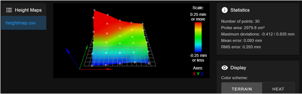
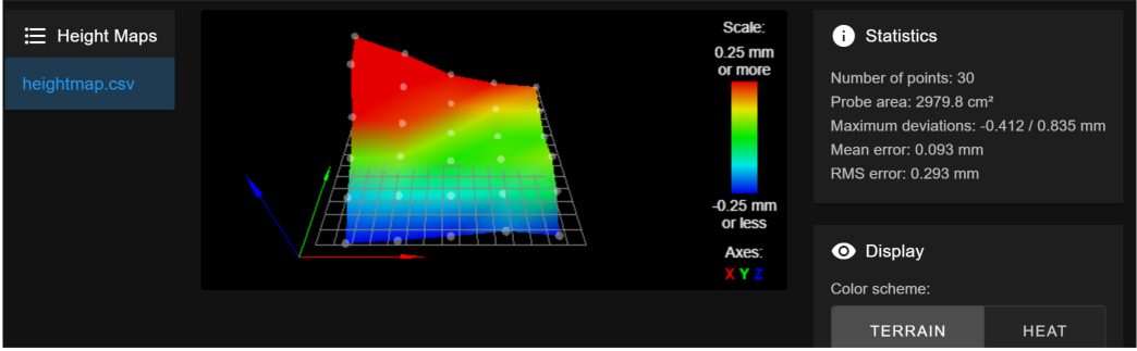
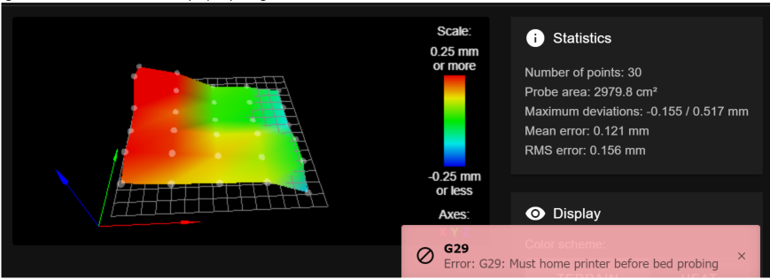
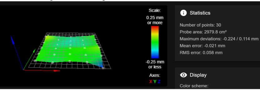
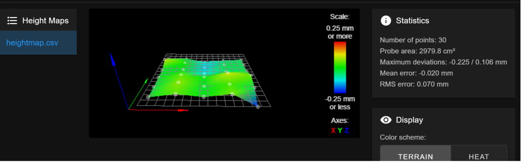
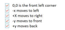
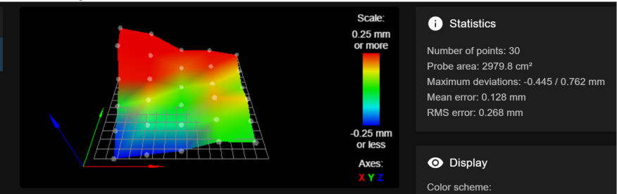
      G29 ; mesh bed leveling 
      G29 S1
      M104 S[first_layer_temperature] ; set extruder temp
      G92 E0.0
      G1 Y0 X0 F4000
      G1 Z3 F720
      M109 S[first_layer_temperature] ; wait for extruder temp
      
      ; intro line
      G1 X0 F1000
      G1 Z0.2 F720
      G1 X60 E38.0 F900
      G1 X130 E30.0 F700
      G92 E0.0


      Let me know if anything else would be helpful.

      posted in Tuning and tweaking
      singhm29undefined
      singhm29
    • Very confused with Duet mesh level correction

      I feel like something is very off or maybe I am just silly and haven't been understanding this correctly. After getting my printer setup with a Duet 3 6HC and BLtouch I had some success. However after laying dormant for a month I went to start a print only to find my bed level compensation wasnt quite correct when I started a full bed print 600x600mm. This led me down a rabbit hole which I now have many questions about.

      1.My original thought was to just bring the nozzle closer to the print bed through Prusaslicer Z offset but after increasing by -0.4 I realized something else was wrong. I homed my Z axis and checked if Z=0 left only a gap large enough for a piece of paper to slide under. It did not, the gap was much larger. I reset my Z trigger distance by following Betrue3Ds guide probing a single point a number of times and averaging them out. I previously had this as 2.09 and it was now 2.50. Oddly 2.5 is what I had at some other point during my tuning the previous month, I am confused why this keeps changing. I understand why a more negative Z offset in prusaslicer wasnt making any difference as I was already at my Z=0 point but I dont get why this value is changing.

      2.If I probe different points of my bed I get a different trigger height, its repeatable at that point but its not the same between points. I feel like I read somewhere that this should be the same everywhere on the bed.

      3.From this height map the red circled point had a Z height of 0.47mm. I would think that this meant that it was 0.47mm too high and printing in this area would cause the nozzle to print too close to the bed. Instead when I manually set Z=0 at the center of my bed, turned off the motors and manually moved the print bed to this spot it was 0.47mm lower... am I just reading the height map wrong?

      1512a020-8b74-461b-8cac-3c15b805ac50-image.png

      4.I lifted up the red point so that it just caught a piece of paper to be better in line with the center of the printer and to minimize the red point however instead of improving it now told me that red point was 0.68mm... to make things odder it prints better now.
      cc46ec03-cf26-4ab0-a668-042f42c06c15-image.png

      Thank you for any insights!

      posted in Tuning and tweaking
      singhm29undefined
      singhm29
    • RE: Bltouch blue light not on during power up but on after homing

      Great! Happy to hear that I might be overreacting and looking in the wrong area. It is indeed working as expected otherwise just wanted to rule out that being an issue.

      This is what produced the height level map above
      M558 P9 C"^io7.in" H5 F120 T6000

      After reading through other posts one of which I believe you commented on I changed to this

      M558 P9 C"^io7.in" H3 F60 T6000 A10 R0.75 S0.003 and this produced

      d40b61f6-f03e-409c-8d58-8c35146b4995-image.png

      Seems like an improvement with multiple probing, one thing I noticed with this new M558 is that at some points it will probe 2-3x but others a single time, how does it decide when greater accuracy is needed?

      G31 P25 X-5 Y48 Z2.67 ; set Z probe trigger value, offset and trigger height
      This is what has been used for both maps

      posted in Duet Hardware and wiring
      singhm29undefined
      singhm29
    • Bltouch blue light not on during power up but on after homing

      Wondering if the behavior im seeing is an indication of something being wrong:

      • I power on my printer
      • Bltouch self tests
      • Bltouch sits at rest with only the RED led on
      • Z axis is homed and occurs successfully (Blue led turns on when probe deploys and then turns red when triggered)
      • BLtouch sits at rest with RED led on AND Blue led is now on

      BLtouch wiring
      2956ac09-154b-4863-945d-41252f8a1b0e-image.png

      Do I need to change a header to activate 5V_Ext for this? Looking at the Duet 3 wiring layout it lists this as 5V_EXT instead of just 5V

      I had asked another user with the same board (Duet 3 6HC) and he said his light was on at power up but since my self test and Z-homing seemed to be working fine I didnt think much of it.

      That is until I realized my heightmap was very bad.
      ea643fab-3c4d-451f-aa7c-8884cd9bca4f-image.png

      I've noticed that during probing this again differs from what I see on my Marlin machines. I'm using Marlin as my reference as this is my first dive into Duet 3 bed leveling and I have it working well on the Marlin side with BLtouch.

      Marlin

      • Solid red when moving between probing points
      • Blue when probe is deployed
      • Red when probe is triggered and it remains red until the next probing event

      Duet 3

      • Solid red when moving between probing points
      • Blue when probe is deployed
      • Red when probe is triggered but at some points it flashes red off for a split second and then turns back on until the next probe point

      This difference in probing behavior during G29 makes me think that is contributing to my poor height map paired with the weirdness I see during power up. I'm sure I have something off in my bed/config files but thinking I might need to figure the wiring out first. Open to any suggestions!

      Board: Duet 3 6HC
      Firmware: MB6HC 3.2 (2021-01-05)
      DWC 3.2.0

      posted in Duet Hardware and wiring
      singhm29undefined
      singhm29