First layer level issues delta
-
Hi,
After upgrading my Anycubic predator to a duet wifi with mag ball arms and smart effector I cannot get a decent first layer.
This is the first time I am using the duet, the smart effector and duet wifi and mag ball arms are installed at once.
Before the upgrade I had no issues getting a good first layer after some playing around with the baby steps. The main reason was that is was inconsistent and temperamental. Also some prints went wrong half way without reason by shifting along the X or Y axis. Because of the amount of use and time spent on those things wen it went wrong again I decided to upgrade.After some advice here on the forum I used the auto delta calibration to set the parameters in config.g
After that did a mesh level compensation. After that started the print, but the first layer is not consistent, at some points it is scraping the bed, and at other points the layer lets go of the bed.

The mesh level compensation looks something like this:
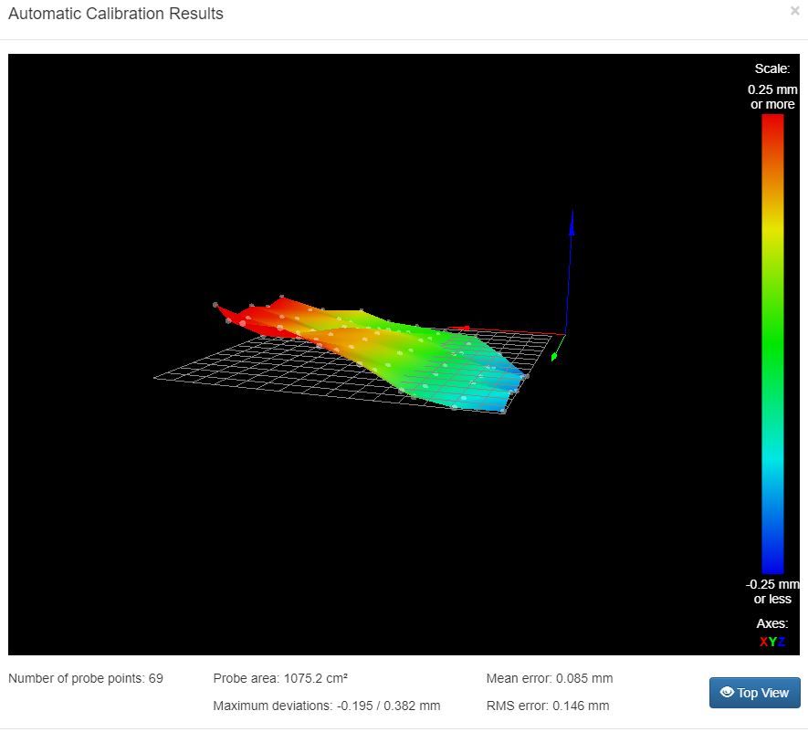
This same tilt is always there, also after the auto delta calibration.
Also below the config.g file I am using at the moment.
I hope the forum can help me resolve these issues, if you need any more information please let me know.; Configuration file for Duet WiFi (firmware version 2.03)
; executed by the firmware on start-up
;
; generated by RepRapFirmware Configuration Tool v2.1.3 on Sat Dec 07 2019 21:21:10 GMT+0100 (Midden-Europese standaardtijd); General preferences
G90 ; send absolute coordinates...
M83 ; ...but relative extruder moves
M550 P"Predator" ; set printer name
M665 R227.865 L440.5 B185 H418.866 ; Set delta radius, diagonal rod length, printable radius and homed height
M666 X0.171 Y0.129 Z0 ; put your endstop adjustments here, or let auto calibration find them; Network
M552 S1 ; enable network
M586 P0 S1 ; enable HTTP
M586 P1 S0 ; disable FTP
M586 P2 S0 ; disable Telnet; Drives
M569 P0 S0 ; physical drive 0 goes backwards
M569 P1 S0 ; physical drive 1 goes backwards
M569 P2 S0 ; physical drive 2 goes backwards
M569 P3 S1 ; physical drive 3 goes forwards
M584 X0 Y1 Z2 E3 ; set drive mapping
M350 X16 Y16 Z16 E16 I1 ; configure microstepping with interpolation
M92 X80.00 Y80.00 Z80.00 E400.00 ; set steps per mm
M566 X1200.00 Y1200.00 Z1200.00 E1200.00 ; set maximum instantaneous speed changes (mm/min)
M203 X18000.00 Y18000.00 Z18000.00 E1200.00 ; set maximum speeds (mm/min)
M201 X1000.00 Y1000.00 Z1000.00 E1000.00 ; set accelerations (mm/s^2)
M906 X1000 Y1000 Z1000 E800 I30 ; set motor currents (mA) and motor idle factor in per cent
M84 S30 ; Set idle timeout; Axis Limits
M208 Z0 S1 ; set minimum Z; Endstops
M574 X2 Y2 Z2 S1 ; set active high endstops; Z-Probe
M558 P8 R0.5 A3 S0.02 H3 F200 T6000 ; set Z probe type to effector and the dive height + speeds
G31 P100 X0 Y0 Z0 ; set Z probe trigger value, offset and trigger height
M557 R185 S40 ; define mesh grid; Heaters
M305 P0 T100000 B4138 R4700 ; set thermistor + ADC parameters for heater 0
M143 H0 S120 ; set temperature limit for heater 0 to 120C
M305 P1 T100000 B4138 R4700 ; set thermistor + ADC parameters for heater 1
M143 H1 S280 ; set temperature limit for heater 1 to 280C; Fans
M106 P1 S1 I0 F500 H1 T45 ; set fan 0 value, PWM signal inversion and frequency. Thermostatic control is turned on
M106 P1 S1 I0 F500 H-1 ; set fan 1 value, PWM signal inversion and frequency. Thermostatic control is turned off; Tools
M563 P0 D0 H1 F0 ; define tool 0
G10 P0 X0 Y0 Z0 ; set tool 0 axis offsets
G10 P0 R0 S0 ; set initial tool 0 active and standby temperatures to 0C; Custom settings are not defined
; Miscellaneous
M911 S10 R11 P"M913 X0 Y0 G91 M83 G1 Z3 E-5 F1000" ; set voltage thresholds and actions to run on power loss -
Have you followed the instruction here https://duet3d.dozuki.com/Wiki/Calibrating_a_delta_printer
-
This is a good page for understanding why the bed shape is the way it is: http://boim.com/DeltaUtil/CalDoc/Calibration.html
Ian
-
What mechanism is being used to level the bed? IR Sensor? Piezo? Smart Effector? BLTouch? Something else?
Can you also post your bed.g file? That will show us which (and how many) points your probing, as well as the type of leveling you are doing.
Take care
Gary -
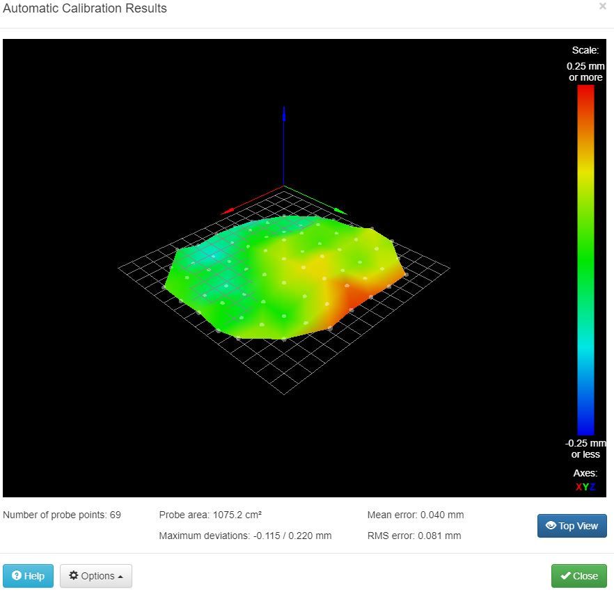
Thanks for the help so far. I did mix up the XYZ values of M665 and M666. So that is done correctly now (I think ;))
M665 R227.9 L440.48 B185 H418.879 X0.217 Y0.125 Z0 ; Set delta radius, diagonal rod length, printable radius and homed height
M666 X0.3 Y-0.08 Z0 ; put your endstop adjustments here, or let auto calibration find themThis does does make the level a lot better when starting the mesh grid compensation
However the root problem stays the same. The first layer is better with the mesh compensation not activated. But in both cases not as good as the standart predator.
Here the bed.g:
; bed.g
; called to perform automatic delta calibration via G32
;
; generated by RepRapFirmware Configuration Tool v2.1.3 on Sat Dec 07 2019 21:21:10 GMT+0100 (Midden-Europese standaardtijd)
M561 ; clear any bed transform
; Probe the bed at 6 peripheral and 6 halfway points, and perform 6-factor auto compensation
; Before running this, you should have set up your Z-probe trigger height to suit your build, in the G31 command in config.g.
G30 P0 X0.00 Y185.00 Z-99999 H0
G30 P1 X118.92 Y141.72 Z-99999 H0
G30 P2 X182.19 Y32.12 Z-99999 H0
G30 P3 X160.21 Y-92.50 Z-99999 H0
G30 P4 X63.27 Y-173.84 Z-99999 H0
G30 P5 X-63.27 Y-173.84 Z-99999 H0
G30 P6 X-160.21 Y-92.50 Z-99999 H0
G30 P7 X-182.19 Y32.12 Z-99999 H0
G30 P8 X-118.92 Y141.72 Z-99999 H0
G30 P9 X0.00 Y92.50 Z-99999 H0
G30 P10 X80.11 Y46.25 Z-99999 H0
G30 P11 X80.11 Y-46.25 Z-99999 H0
G30 P12 X0.00 Y-92.50 Z-99999 H0
G30 P13 X-80.11 Y-46.25 Z-99999 H0
G30 P14 X-80.11 Y46.25 Z-99999 H0
G30 P15 X0 Y0 Z-99999 S6
; Use S-1 for measurements only, without calculations. Use S4 for endstop heights and Z-height only. Use S6 for full 6 factors
; If your Z probe has significantly different trigger heights depending on XY position, adjust the H parameters in the G30 commands accordingly. The value of each H parameter should be (trigger height at that XY position) - (trigger height at centre of bed) -
I am using a smart effector by the way.
If I would run an auto delta calibration just before each print, can I save the results somehow? Now I just write them down and change the config.g. But then I have to restart and home again. And after each homing I have slightly different results. -
@Lakeman you can type in M500 to record the results to config-override.g
Then make sure you have M501 at the end of config.g and the overridden values will be loaded on start up -
You don't HAVE to use mesh compensation when printing (or at all.) I run it once in a while on my own machine just to look at the pretty picture (to see if there are any problems going on that I'm not aware of - such as too much backlash.)
In my opinion, mesh compensation on a delta printer is a work-around for an uneven bed, and would be better solved with a flat build surface.
You also really don't have to run auto-calibration for every print. If you run auto-calibration and save the values via M500 (and your config.g contains a M501 at the end), a simple G28 to home your printer will have everything ready to print (assuming you have decent endstops on the delta towers.)
My typical workflow is to only run an auto-calibration when I'm changing filament. While I have no filament loaded (and so nothing is oozing) I heat up the bed and nozzle, clean the nozzle, and run an auto-calibration a couple times until the values stabilize. I then save it via M500 and ONLY run G28 before a print (not G32.) This saves me the annoyance of bad auto-calibrations that occur from filament stuck to the nozzle or oozing out.
-
It does work without mesh compensation. Increased the thickness of the first layer a bit to smooth out any imperfections, and that seems to work alright. On the origional predator I only used to level the bed when it goes to far of again, and the probe has to be installed seperately, so I also do not zero the bed, only the endstops on top. This usually works fine for a week and up to a month sometimes.
I will try to use the duet without mesh and see how it goes. If anybody has an idea why the mesh does not work I am still interessted.