Second tool not showing up in DWC with firmware 3.0
-
Hi,
after upgrading the DuetFirmware from 2.05 to stable 3.0 my second tool is missing.
I set up the sensors and heaters according to firmware 3.0. Not everything is finished yet but as I said I struggle with the second tool and don't know what wrong.config.g
; Configuration file for Duet WiFi (firmware version 1.20 or newer)
; executed by the firmware on start-up
;
; generated by RepRapFirmware Configuration Tool on Mon Mar 05 2018 12:33:27 GMT+0100 (CET)

; GENERAL PREFERENCES
G90                                       ; Send absolute coordinates...
M83                                       ; ...but relative extruder moves

; NETWORK
M550 PUMO+                                ; Set machine name
M551 PChrissa1                            ; Set password
M552 S1                                   ; Enable network
;*** Access point is configured manually via M587
M586 P0 S1                                ; Enable HTTP
M586 P1 S0                                ; Disable FTP
M586 P2 S0                                ; Disable Telnet

; DRIVES
M569 P0 S1                                ; Drive 0 goes forwards (X)
M569 P1 S1                                ; Drive 1 goes forwards (Y)
M569 P2 S1                                ; Drive 2 goes forwards (Z)
M569 P3 S0                                ; Drive 3 goes backwards (E0)
M569 P4 S1                                ; Drive 4 goes forwards (E1)
M350 X64 Y64 Z256 E256:256 I0             ; Configure microstepping without interpolation
M92 X320 Y320 Z6400 E7879.2:7879.2        ; Set steps per mm
M566 X720 Y720 Z24 E300                   ; Set maximum instantaneous speed changes (mm/min)
M203 X18000 Y18000 Z1800 E6000            ; Set maximum speeds (mm/min)
M201 X1600 Y1600 Z100 E10000              ; Set accelerations (mm/s^2)
M906 X1300 Y1300 Z1300 E1200 I50          ; Set motor currents (mA) and motor idle factor in per cent
M84 S30                                   ; Set idle timeout

; AXIS LIMITS
M208 X0 Y0 Z0 S1                          ; Set axis minima
M208 X185 Y180 Z180 S0                    ; Set axis maxima

; ENDSTOPS
M574 X1 Y1 Z1 S0                          ; Set active low endstops
M558 P0 H5 F120 T6000                     ; Set Z probe type to switch and the dive height + speeds
G31 P0 X0 Y0 Z0                           ; Set Z probe trigger value, offset and trigger height
M557 X0:185 Y0:180 S20                    ; Define mesh grid

; HEATERS
; Heated Bed
M308 S0 P"spi.cs2" Y"rtd-max31865"	  ; define sensor
M950 H0 C"bedheat" T0			  ; define heater
M307 H0 A135.4 C792.7 D1.1 S1.00 V24.3 B1 ; Use bang-bang control for heated bed
M143 H0 S135                              ; Set temperature limit for heated bed to 135C
; Main Nozzle
M308 S1 P"spi.cs1" Y"rtd-max31865"        ; define sensor
M950 H1 C"e0heat" T1			  ; define heater
M307 H1 A914.2 C355.3 D3.6 S1.00 V24.2 B0 ; Use PID control for Heater 1
M143 H1 S385                              ; Set temperature limit for Heater 0 to 385C
; Support Nozzle
M308 S2 P"spi.cs3" Y"rtd-max31865"	  ; define sensor
M950 H2 C"e1heat" T2			  ; define heater
M307 H2 A702.7 C370.9 D4.4 S1.00 V24.1 B0 ; Use PID control for Heater 2
M143 H2 S385				  ; Set temperature limit for Heater 1 to 385C
; Heated Chamber
M141 H3					  ; Heater 3 is chamber heater
M308 S3 P"spi.cs4" Y"rtd-max31865"	  ; define sensor
M950 H3 C"!exp.heater3" T3
M307 H3 A58.3 C63.1 D4.2 S1.00 V24.4 B1	  ; Use bang-bang control for heated chamber
M143 H3 S120      			  ; Set temperature limit for heated chamber to 120C


; FANS
M106 P0 S0.5 H-1 C"Electronics cooling"   ; Set fan 0 value, PWM signal inversion and frequency. Thermostatic control is turned off
M106 P1 S0 F40 H-1 C"Driver cooling"      ; Set fan 1 value, PWM signal inversion and frequency. Thermostatic control is turned off
M106 P2 S1 F5000 H-1 C"LEDs"	          ; Set fan 2 value, PWM signal inversion and frequency. Thermostatic control is turned off


; TOOLS
M563 P0 D0 H1 S"Main"              	  ; Define tool 0
G10 P0 X0 Y0 Z0                           ; Set tool 0 axis offsets
G10 P0 R0 S0                              ; Set initial tool 0 active and standby temperatures to 0C
M563 P1 D1 H2 S"Support"                  ; Define tool 1
G10 P1 X20 Y0 Z0                          ; Set tool 1 axis offsets
G10 P1 R0 S0                              ; Set initial tool 1 active and standby temperatures to 0C


; ADDITIONAL TEMPERATURE SENSORS


; MISCELLANEOUS
M912 P0 S-2.7                             		; Calibrating the CPU temperature
M572 D0 S0.15				 	 	; Activate pressure advance
M572 D1 S0.15				  		; Activate pressure advance
M911 S22.8 R23.5 P"M913 X0 Y0 G91 M83 G1 Z3 E-5 F1000" 	; Configure Auto save
M915 P0:1:2 S3 F0 H200 R1				; Configure stall detection for X,Y and Z
M140 S0					  		; Set heated bed to 0°C (to activate it)
M141 S0					  		; Set heated chamber to 0°C (to activate it)
M501					  		; Use the config-override values
T1                                        		; Select second tool
T0                                        		; Select first tool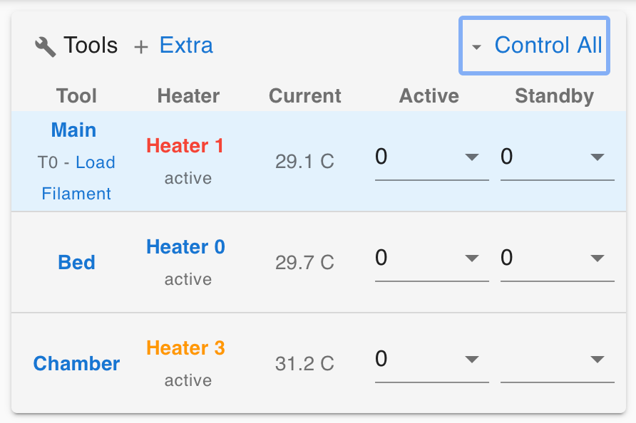
T0 is there, T1 is missing -
copy/paste your various definition commands, like m503, one at a time, into the DWC console. See if you get any error messages.
Also, there is a panel on DWC that has sliders for what is/isn't shown. If I recall, it is a right click on the screen you've shown above...
-
@Christoph13524 You don't have an M584 command in your config.g. https://duet3d.dozuki.com/Wiki/Gcode?revisionid=HEAD#Section_M584_Set_drive_mapping
In RRF3 on Duet 2, only X, Y, Z and E0 are defined by default. So you're missing E1. AddM584 X0 Y1 Z2 E3:4at the beginning of the 'DRIVES' section.Ian
Bed-slinger - Mini5+ WiFi/1LC | RRP Fisher v1 - D2 WiFi | Polargraph - D2 WiFi | TronXY X5S - 6HC/Roto | CNC router - 6HC | Tractus3D T1250 - D2 Eth
-
@droftarts
thanks! That was the problem