3 independent Z motors issue
-
Hello
I usually research a lot before posting a question, this is why this is my first post.
I’ve built myself a pretty stable core xy, until I decided to upgrade to linear rails which turned out good however I have a slight Y tilt sensitivity which I thought I can correct it easily by adding a 3rd Z motor.My problem is that one of the lead screws has a different pitch, which requires different steps/mm for the new motor.
I did find a solution, to define the 3rd motor into a new axis, U, and define the new steps/mm accordingly. Did it, tested it separately and works fine, as an independent motor.
What I cannot figure out is how make the U motor move when I issue a Z command, like when jogging Z in DWC.
Any help or hint is highly appreciated.
-
Haven't you found that guide?
https://duet3d.dozuki.com/Wiki/Bed_levelling_using_multiple_independent_Z_motors#Section_Example_for_3_motors -
Cheers for the reply. Of course I've seen it... But it doesn't necessarily fix the issue... if i would apply this guide I would lose the ability to jog Z, well i could but it would just move the motors assigned to Z... and what still eludes me.. how would this behave in a print... would i have to do some settings in my slicer?
I believe normally i could just declare 3 motors to the Z is they would be the same and have the same kind of lead screws, but if i declare a new axis for the third motor, this would mean that whenever Z is mentioned U must follow... and I wounder if it would be a simpler solution to this, like U just follows any Z movement. It would have been a lot easier if Z would allow for different steps/mm like E does.
Here is a rough sketch of my configuration:
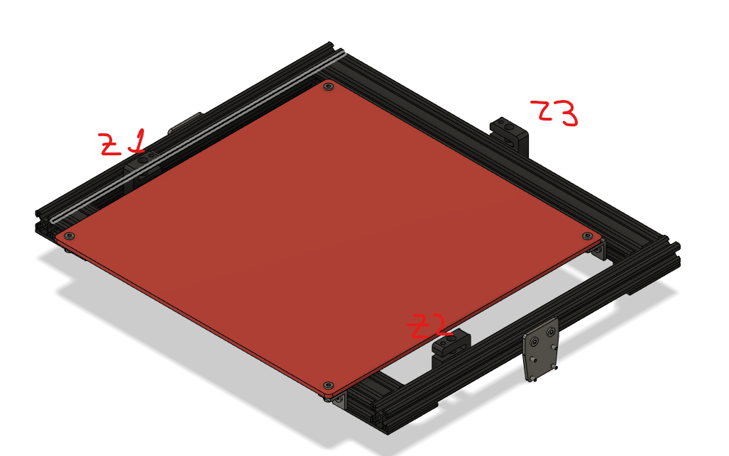
Z1 and Z2 have an 4mm/rev screw, motor is 1,8 deg which results in 800 steps/mm
Z3 is a 2mm/rev on 1.8deg which leads to 1600 steps/mmAnd this is a snippet form my config.g
; Drives
M569 P0 S1                                         ; Drive 0 goes fwd
M569 P1 S1                                         ; Drive 1 goes backwards
M569 P2 S0                                         ; Drive 2 goes backwards
M569 P3 S1                                         ; Drive 3 goes backwards
M569 P4 S0                                         ; Drive 4 goes backwards
M569 P5 R1 T2.5:2.5:5:0 S0                        ; External Drive 5 goes backwards
M584 X0 Y1 Z2:4 U3 E5 				   ; two Z motors connected to driver outputs Z and E1 and two E motors E0 and E2
M350 X16 Y16 Z16 U16 E16 I1                            ; Configure microstepping with interpolation
M92 X160.00 Y160.00 Z798.8 U1600		   	   ; Set steps per mm for XYZ
M92 E396	               			   ; Set steps per mm for extruders
M566 X800.00 Y800.00 Z12 U12 E300 		           ; Set maximum instantaneous speed changes (mm/min)
M203 X12000.00 Y12000.00 Z600 U600 E2400 	           ; Set maximum speeds (mm/min)
M201 X1500.00 Y1500.00 Z20 U20 E1500 	           ; Set accelerations (mm/s^2)
M906 X1200.00 Y1200.00 Z1200 U1200 E800 I30     	   ; Set motor currents (mA) and motor idle factor in per cent
M84 S30                                            ; Set idle timeout
With this I get the possibility to jog U axis in the main screen (which i can suppress with P3 in M584 ) but Z movements are not reflected in Z3 motor (which is mapped to U)
-
@cugetare said in 3 independent Z motors issue:
Z1 and Z2 have an 4mm/rev screw, motor is 1,8 deg which results in 800 steps/mm
Z3 is a 2mm/rev on 1.8deg which leads to 1600 steps/mmthey have to have the same number of steps /mm, try reducing the microstepping on the external motor by a factor of 2
-
RRF doesn't directly support multiple motors on an axis with different steps per mm. But I think you could make it work by defining the additional motor as a U axis and then using the M669 command Z parameter to adjust the matrix to make the U motor move by the correct amount when you move Z. You can hide the U axis in normal use.
Duet WiFi hardware designer and firmware engineer
Please do not ask me for Duet support via PM or email, use the forum
http://www.escher3d.com, https://miscsolutions.wordpress.com -
@cugetare said in 3 independent Z motors issue:
Cheers for the reply.
As I’m planning the modification of my Z-axis, I have just looked in this thread.
Standard seems to be realy easy, but I had not realized that M92 is related to the axis and not to the drives.
No hard feelings. -
@dc42 said in 3 independent Z motors issue:
RRF doesn't directly support multiple motors on an axis with different steps per mm. But I think you could make it work by defining the additional motor as a U axis and then using the M669 command Z parameter to adjust the matrix to make the U motor move by the correct amount when you move Z. You can hide the U axis in normal use.
Thanks for the hint DC.
I assume i should define M669 K5 (CoreXYU) X1:0:0 Y0:1:0 Z0:0:1 U0:0:0.5
Right? -
@cugetare said in 3 independent Z motors issue:
Thanks for the hint DC.
I assume i should define M669 K5 (CoreXYU) X1:0:0 Y0:1:0 Z0:0:1 U0:0:0.5
Right?If it's a Cartesian machine and you set up Z and U with the correct steps/mm in both cases, then I think you want X1:0:0:0 Y0:1:0:0 Z0:0:1:1 U0:0:0:1. Then use M584 P3 to hide the U axis.
Duet WiFi hardware designer and firmware engineer
Please do not ask me for Duet support via PM or email, use the forum
http://www.escher3d.com, https://miscsolutions.wordpress.com -
@dc42 said in 3 independent Z motors issue:
@cugetare said in 3 independent Z motors issue:
Thanks for the hint DC.
I assume i should define M669 K5 (CoreXYU) X1:0:0 Y0:1:0 Z0:0:1 U0:0:0.5
Right?If it's a Cartesian machine and you set up Z and U with the correct steps/mm in both cases, then I think you want X1:0:0:0 Y0:1:0:0 Z0:0:1:1 U0:0:0:1. Then use M584 P3 to hide the U axis.
Hi DC
I tried your advice and the movement looks better (did some changes though i have a coreXY). Sorry for the delay, i ran into some issues with the bed probing, looks like EMF in the cable is not appreciated by BLTouch. some rewiring and some ferrites later i could make a foolish attempt at homing the thing... which kind of fails... i will paste my config and my homing files hoping someone can point me to the mistake i overlooked.
I can explain a little about the behavior. My setup was configured with senseless homing for X and Y so the machine would first home X then Y then go in the middle of the bed and home Z.
NOW.... after XY homing head is positioning in the middle of the deploying the probe waiting for the bed to touch it, Z(with 2 motors) and U(with 1 motor) are moving in sync until BLTouch is triggered, but sometimes U continues to move... I know i'm making a mistake... i just don't see where....This is my config.g as of now
; General preferences
G90                                                ; Send absolute coordinates...
M83                                                ; ...but relative extruder moves

;M667 S1                                            ; Select CoreXY mode
M669 K5  X1:1:0:0 Y1:-1:0:0 Z0:0:1:1 U0:0:0:1		; custom axes

; Network
; left out

; Drives
M569 P0 S1                                         ; Drive 0 goes fwd
M569 P1 S1                                         ; Drive 1 goes backwards
M569 P2 S0                                         ; Drive 2 goes backwards
M569 P3 S1                                         ; Drive 3 goes backwards
M569 P4 S0                                         ; Drive 4 goes backwards
M569 P5 R1 T2.5:2.5:5:0 S0                        ; External Drive 5 goes backwards
M584 X0 Y1 Z2:4 U3 E5 P3			   ; two Z motors connected to driver outputs Z and E1 and two E motors E0 and E2
M350 X32 Y32 Z16 U16 E16 I1                            ; Configure microstepping with interpolation
M92 X320.00 Y320.00 Z798.8 U1600		   	   ; Set steps per mm for XYZ
M92 E396	               			   ; Set steps per mm for extruders
M566 X800.00 Y800.00 Z12 U12 E300 		           ; Set maximum instantaneous speed changes (mm/min)
M203 X12000.00 Y12000.00 Z600 U600 E2400 	           ; Set maximum speeds (mm/min)
M201 X1500.00 Y1500.00 Z20 U20 E1500 	           ; Set accelerations (mm/s^2)
M906 X1200.00 Y1200.00 Z1200 U1200 E800 I30     	   ; Set motor currents (mA) and motor idle factor in per cent
M84 S30                                            ; Set idle timeout

; Axis Limits
M671 X-50:150:340 Y140:320:140 S3        ; leadscrews at left and right of X axis
M208 X-28:280 Y0:300 Z0:250 U0:250	 ; axis min and max


; Endstops
M574 X1 Y1 S3                                      ; Set active low endstops
M915 P0 P1 S3 F0   				   ; configure stall detection


; Z-Probe
M307 H3 A-1 C-1 D-1 				             ; Disable the 3rd Heater
M574 Z1 U1 S2                                                  ; Set endstops controlled by probe
M558 P9 H5 F1000 T12000		             ; Set Z probe type/mode 5. H=Dive Height. F=Speed the bed moves
G31 X0 Y25 Z2.1 U2.1 P25	                             ;  Set Z probe trigger value, offset and trigger height
M557 X27.5:286 Y5:285 S80                            ; Define mesh grid

; Heaters
M307 H0 B0 S1.00 F50                                   ; Disable bang-bang mode for the bed heater and set PWM limit
M143 H0 S140                                                 ; Set temperature limit for heater 0 to 120C
M143 H1 S280                                                 ; Set temperature limit for heater 1 to 280C

; My Fans
M106 P0 S0.3 I0 F200 H0 T45                          ; Set fan 0 value, PWM signal inversion and frequency. TC -> ON
M106 P1 S0.5 I0 F200 H1 T85                          ; Set fan 1 value, PWM signal inversion and frequency. TC -> ON
M106 P2 S0.3 I0 F200 H0 T45                          ; Set fan 2 value, PWM signal inversion and frequency. TC -> ON

; Tools
M563 P0 D0 H1 F0:2                                ; Define tool 0
G10 P0 X0 Y-20 Z0                                   ; Set tool 0 axis offsets
G10 P0 R0 S0                                      ; Set initial tool 0 active and standby temperatures to 0C


; Automatic power saving
M911 S20 R22 P"M913 X0 Y0 G91 M83 G1 Z3 E-5 F1000" ; Set voltage thresholds and actions to run on power loss

; Custom settings are not configured

; Miscellaneous
M501                                            ; Load saved parameters from non-volatile memory
T0                                                 ; Select first tool
M280 P3 S120 I1                        ; BLTouch force self test
G4 S2                                           ; for 2 secs
M280 P3 S90 I1                          ; then retract
This is my homeall.g as of now
G91            		; relative positioning
G1 S2 Z5 F200 		; lower Z relative to current position
G90            		; absolute positioning
M98 P/sys/homex.g
M98 P/sys/homey.g
G1 X150 Y150 F6000          		; go to first bed probe point and home Z
G30 S-1                    		; home Z by probing the bed
G92 Z2.1  ;U2.1
G1 H2 Z5 U5 F100
G1 X0 Y0 F6000         	; go back home XY
Homex.g (home y is the same but for y homing)
M400					; make sure everything has stopped before we make changes
M915 P0:1 S3 F0 R0			; configure stall detection
M574 X1 Y1 S3				; set endstops to use motor stall
M913 X50 Y50				; reduce motor current to 50% to prevent belts slipping
M201 X500				; reduce acceleration to avoid false triggering
G91					; use relative positioning
G1 S1 X-325 F4000		      	; move towards axis minimum
G1 X5                      		; move away from home
M400                  			; make sure everything has stopped before we reset the motor currents
M913 X100 Y100 				; motor currents back to 100%
G90                   			; back to absolute positioning
M574 X1 Y1 S1
homez.g
G91 ; relative positioning G1 S2 Z5 F200 ; lower Z relative to current position G90 ; absolute positioning G1 X150 Y150 F6000 ; go to first bed probe point and home Z G30 S-1 ; home Z by probing the bed G92 Z2.1 ;U2.1 G1 H2 Z5 U5 F100 G1 X0 Y0 F6000 ; go back home XY -
I think this looks like a needle in hay stack kind of thing so let me simplify my doubts...
After defining the U axis withM669 K5 X1:1:0:0 Y1:-1:0:0 Z0:0:1:1 U0:0:0:1And specifying the motor assignments and steps pr mm:
M350 X32 Y32 Z16 U16 E16 I1                             ; Configure microstepping with interpolation
M92 X320.00 Y320.00 Z798.8 U1597.6		   	   			; Set steps per mm for XYZ
then speed, jerk, acc
M566 X800.00 Y800.00 Z12 U12 E300 		           		; Set maximum instantaneous speed changes (mm/min)
M203 X12000.00 Y12000.00 Z600 U600 E2400 	            ; Set maximum speeds (mm/min)
M201 X1500.00 Y1500.00 Z20 U20 E1500 	          		; Set accelerations (mm/s^2)
Should i also mention U in:
- axis limits?
M208 X300 Y300 Z0 U0 S0 ; Set axis maxima M208 X0 Y0 Z250 U250 S1 ; Set axis minima- Z probe config?
M574 Z1 U1 S2 ; Set endstops controlled by probe M558 P9 H5 F1000 T12000 ; Set Z probe type/mode 5. H=Dive Height. F=Speed the bed moves G31 X0 Y25 Z2.1 U2.1 P25 ; actual 1.635 Set Z probe trigger value, offset and trigger height- home Z?
- bed.g?
In other words, should i mention U every time Z is also mentioned?
-
@cugetare said in 3 independent Z motors issue:
I think this looks like a needle in hay stack kind of thing so let me simplify my doubts...
After defining the U axis withM669 K5 X1:1:0:0 Y1:-1:0:0 Z0:0:1:1 U0:0:0:1And specifying the motor assignments and steps pr mm:
M350 X32 Y32 Z16 U16 E16 I1                             ; Configure microstepping with interpolation
M92 X320.00 Y320.00 Z798.8 U1597.6		   	   			; Set steps per mm for XYZ
then speed, jerk, acc
M566 X800.00 Y800.00 Z12 U12 E300 		           		; Set maximum instantaneous speed changes (mm/min)
M203 X12000.00 Y12000.00 Z600 U600 E2400 	            ; Set maximum speeds (mm/min)
M201 X1500.00 Y1500.00 Z20 U20 E1500 	          		; Set accelerations (mm/s^2)
Should i also mention U in:
- axis limits?
M208 X300 Y300 Z0 U0 S0 ; Set axis maxima M208 X0 Y0 Z250 U250 S1 ; Set axis minima- Z probe config?
M574 Z1 U1 S2 ; Set endstops controlled by probe M558 P9 H5 F1000 T12000 ; Set Z probe type/mode 5. H=Dive Height. F=Speed the bed moves G31 X0 Y25 Z2.1 U2.1 P25 ; actual 1.635 Set Z probe trigger value, offset and trigger height- home Z?
- bed.g?
In other words, should i mention U every time Z is also mentioned?
I suggest this:
- Define the U axis in M584 in config.g. Initially, don't hide it.
- Set the current, microstepping and steps/mm of all drives including U.
- Then hide U (M584 P3). After that, never mention U again.
Here's an alternative that doesn't involve a U axis, based on your steps/mm ratio being 2:1:
- Define 3 axes and 3 Z motors
- Set the currents, microstepping etc. with the microstepping set to be correct for the U axis
- Redefine Z as having only 2 motors
- Change the Z microstepping by a factor of 2 so that those 2 motors now have the same steps/mm as the third one
- Redefine Z as having 3 motors. After that, don't change the microstepping again.
Caution: if VIN power is lost (under voltage event) but the board doesn't reset, all 3 drives will be reprogrammed with the same microstepping. So I suggest you do the above sequence in homez.h and in homeall.g.
Duet WiFi hardware designer and firmware engineer
Please do not ask me for Duet support via PM or email, use the forum
http://www.escher3d.com, https://miscsolutions.wordpress.com -
@dc42 said in 3 independent Z motors issue:
Define 3 axes and 3 Z motors
Set the currents, microstepping etc. with the microstepping set to be correct for the U axis
Redefine Z as having only 2 motors
Change the Z microstepping by a factor of 2 so that those 2 motors now have the same steps/mm as the third one
Redefine Z as having 3 motors. After that, don't change the microstepping again.Thanks a lot for the help, I was actually thinking that micro-stepping could be the answer but i would have never figured it out alone how exactly to to that. i added the following 3 lines after removing all mentions of the U axis and switching back to M667 S1
M584 Z2:4
M350 Z32
M584 Z2:3:4
works like a champ! even tested the leadscrew self adjustment and works perfectly.