Large Delta printer not homing on an original duet Maestro
-
thanks for your reply,
I did the following:-
sent the command without pressing
-
pressed each of the endstops one at a time and sent the command.
results:


-
-
You can also look at them in real time on the DWC2 web interface. Go to "machine specific" and look on the lower right side (and maybe scroll down).
These update in real time, and you can touch the switches with your finger and see if they change.
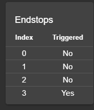
-
This post is deleted! -
all were with one pressed.
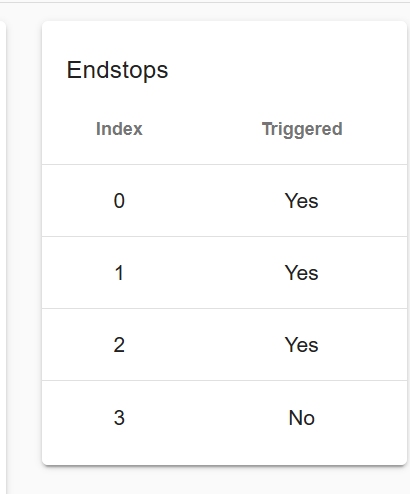
this is what it shows
-
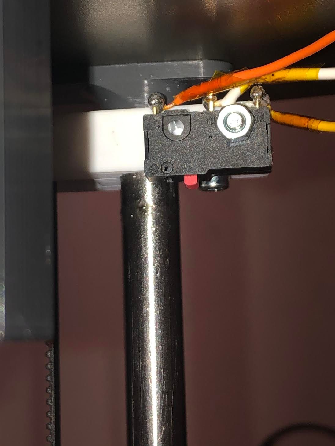
What do the endstops themselves look like? And how do you have them wired/connected? Post a photo maybe?
It looks like from your screen shot that they are showing as triggered when they are not pressed, and showing as not triggered when pressed?
Also it looks like the X endstop doesn't register a press at all?
-
When you change S0 S1, did you reset (or power cycle) the printer?
-
Also, the message when triggered should say "at max stop". Yours says min.
Please re-verify that M574 X2 Y2 Z2 S1
has 2 (two) on each axis, and S1, and that the printer has been restarted.
-
Also, could you copy and paste the contents of your config.g and homing files as text into a post? The screenshots are pretty hard to see and we can't copy and paste from it.
-
i mesured continuity between the left pin and middle pin, when i press the endstop, thats when it conducts. so it is an active high endstop ( left pin and middle pin i am using, left is ground and middle is 3,3v in the board).
( left orange, middle white wires.)
I have checked the config file again and i have restarted the printer after changing S0 to S1 i will include a screenshot.
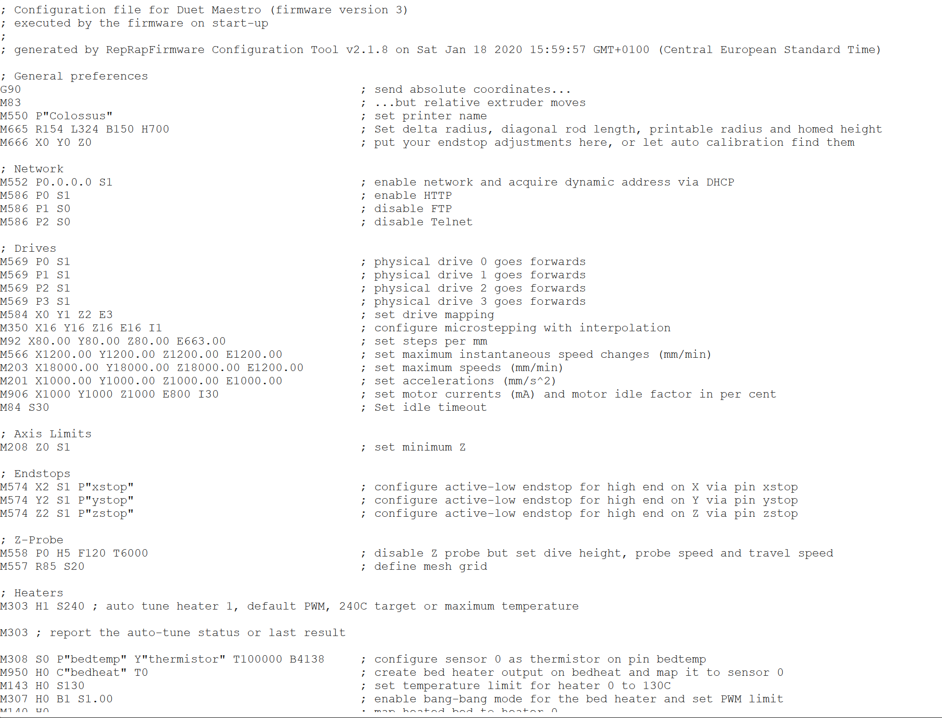
-
@NEVER-LUCKY said in Large Delta printer not homing on an original duet Maestro:
i mesured continuity between the left pin and middle pin, when i press the endstop, thats when it conducts.
If those are the two pins that are wired to the Duet, that is a NO (Normally Open) switch.
I would highly recommend changing the wiring. NC (Normally Closed) switches have lots of advantages. Wire the switch terminals the conduct (per your meter), when the switch is NOT pressed, and the open (per your meter) when the switch is pressed.
There is no third wire.
-
Which board are you using? Duet 2 or Duet 3?
-
im using a duet 2.
what do you mean by "per your meter" ?
im not so familiar with all the terms. -
When you measured continuity.
You want the pins that HAVE continuity when the switch is NOT pressed, and therefore that BREAK continuity when the switch is pressed. This is "normally closed", meaning "normally with continuity"
-
oh, right im doing that right now, do i need to change something in the files or just adjust the wires?
-
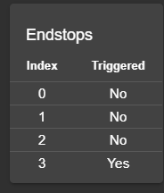
Adjust the wires to be NC, then the S1 should work.
Once you have it adjusted, check this again.
-
alright we are getting someware
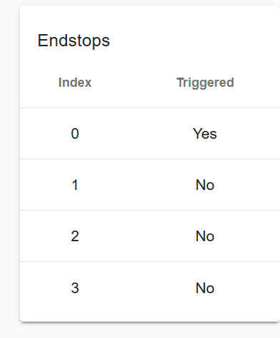
the exruder also has an endstop, should it also be No when i havent loaded any filament?
right now it is saying Yes but i havent loaded filament. the extruder doesnt have the same endstop as the axes so i will have to buy one for it aswell. -
The extruder doesn't really need an endstop. You can use it as a trigger for something else like a filament monitor or runout switch, but it's not required.
-
noted. so now when i press the X endstop it doesnt turn Yes while the Y and Z turn Yes. does it mean the X endstop is busted?
-
possibly. What does it show on your multimeter? Double check your crimps and wire continuity.
-
Yay, that is progress!
And, yes, pursue what @Phaedrux said...