Understanding bed, nozzle and probe boundaries?
-
Hi, I need some help.
I did struggle a bit on my older printer as well but got it working at one time. Now I'm biting my own tale again. Probably because there is a simple fundamental misunderstanding.
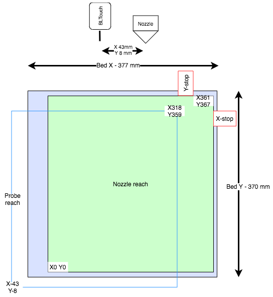
I'm struggling how to configure my Duet 2 and how to avoid probing outside the bed and/ probing as much area as possible.
Does the probe have it's completely own plane relatively to a (the) tool/nozzle.
I made an illustration to help my self as well. Editable draw.io diagram: https://drive.google.com/file/d/1HQhqSgb8IDBUko1jzIApC7QzK2Fqkr1x/view?usp=sharing

config.g
; Configuration file for Duet WiFi (firmware version 3)
; executed by the firmware on start-up
;
; generated by RepRapFirmware Configuration Tool v2.1.8 on Thu Mar 19 2020 21:32:43 GMT+0100 (Central European Standard Time)

; General preferences
G90                                            ; send absolute coordinates...
M83                                            ; ...but relative extruder moves
M550 P"Stians Ender 5 Plus Titan"                            ; set printer name
M918 P1 E4 F2000000                            ; configure direct-connect display

; Network
M552 P0.0.0.0 S1                               ; enable network and acquire dynamic address via DHCP
M586 P0 S1                                     ; enable HTTP
M586 P1 S1                                     ; disable FTP
M586 P2 S1                                     ; disable Telnet

; Drives
M569 P0 S0                                     ; physical drive 0
M569 P1 S0                                     ; physical drive 1
M569 P2 S0                                     ; physical drive 2
M569 P3 S1                                     ; physical drive 3 goes backwards
M569 P4 S0                                     ; physical drive 3
M584 X0 Y1 Z2:4 E3                             ; drive mapping, two Z motors connected to driver outputs Z and E1
M350 X16 Y16 Z16 E16 I1                        ; configure microstepping with interpolation
M92 X80.00 Y80.00 Z800.00 E396.38              ; set steps per mm
M566 X1200.00 Y1200.00 Z24.00 E300.00          ; set maximum instantaneous speed changes (mm/min)
M203 X9000.00 Y9000.00 Z240.00 E6000.00        ; set maximum speeds (mm/min)
M201 X500.00 Y500.00 Z100.00 E5000.00          ; set accelerations (mm/s^2)
M906 X400 Y400 Z400:400 E500 I30               ; set motor currents (mA) and motor idle factor in per cent
M84 S30                                        ; Set idle timeout

; dual z
M671 X-31:384 Y184:184 S2 ; leadscrews at left (connected to Z) and right (connected to E1) of X axis

; Axis Limits
M208 X0 Y0 Z0 S1                               ; set axis minima
M208 X361 Y367 Z400 S0                         ; set axis maxima

; Endstops
M574 X2 S1 P"xstop"                            ; configure active-high endstop for low end on X via pin xstop
M574 Y2 S1 P"ystop"                            ; configure active-high endstop for low end on Y via pin ystop
M574 Z1 S2                                     ; configure Z-probe endstop for low end on Z

; Z-Probe
M950 S0 C"exp.heater3"                         ; create servo pin 0 for BLTouch
M558 P9 C"zprobe.in+zprobe.mod" H5 F120 T6000 A3 ; set Z probe type to bltouch and the dive height + speeds
G31 P500 X43 Y8 Z2.5                          ; set Z probe trigger value, offset and trigger height
M557 X50:361 Y25:367 S30                       ; define mesh grid

; Heaters
M308 S0 P"bedtemp" Y"thermistor" T100000 B4092 ; configure sensor 0 as thermistor on pin bedtemp
M950 H0 C"bedheat" T0                          ; create bed heater output on bedheat and map it to sensor 0
M143 H0 S120                                   ; set temperature limit for heater 0 to 150C
M307 H0 B0 S1.00                               ; disable bang-bang mode for the bed heater and set PWM limit
M140 H0                                        ; map heated bed to heater 0
M308 S1 P"e0temp" Y"thermistor" T100000 B4092  ; configure sensor 1 as thermistor on pin e0temp
M950 H1 C"e0heat" T1                           ; create nozzle heater output on e0heat and map it to sensor 1
M143 H1 S275                                   ; set temperature limit for heater 1 to 275C
M307 H1 B0 S1.00                               ; disable bang-bang mode for heater  and set PWM limit

; System temp sensors
M308 S2 Y"drivers" A"DRIVERS"  ; configure sensor 2 as temperature warning and overheat flags on the TMC2660 on Duet
M308 S3 Y"mcu-temp" A"MCU" ; configure sensor 3 as thermistor on pin e1temp for left stepper

; Fans
M950 F0 C"fan0" Q5000                            ; create fan 0 on pin fan0 and set its frequency
M106 P0 S0 H-1                                  ; set fan 0 value. Thermostatic control is turned off
M950 F1 C"fan1" Q5000                            ; create fan 1 on pin fan1 and set its frequency
M106 P1 S1 H1 T45                               ; set fan 1 value. Thermostatic control is turned on
M950 F2 C"fan2" Q5000                            ; create fan 2 on pin fan2 and set its frequency
M106 P2 H2:3 L0.3 X1 B0.3 T30:60               ; set fan 2 value
M950 F3 C"e1heat" Q9000
M106 P3 L2 X100 B0.3 S12

; Tools
M563 P0 D0 H1 F0                               ; define tool 0
G10 P0 X0 Y0 Z0                                ; set tool 0 axis offsets
G10 P0 R0 S0                                   ; set initial tool 0 active and standby temperatures to 0C

; Custom settings are not defined

; Miscellaneous
M501                                           ; load saved parameters from non-volatile memory
T0                                             ; select first tool
bed.g
; bed.g ; called to perform automatic bed compensation via G32 ; ; generated by RepRapFirmware Configuration Tool v2.1.8 on Thu Mar 19 2020 21:32:43 GMT+0100 (Central European Standard Time) ;M561 ; clear any bed transform ;G29 ; probe the bed and enable compensation ; from https://duet3d.dozuki.com/Wiki/Bed_levelling_using_multiple_independent_Z_motors G28 ; home ;M401 ; deploy Z probe (omit if using bltouch) G30 P0 X25 Y175 Z-99999 ; probe near a leadscrew, half way along Y axis G30 P1 X375 Y175 Z-99999 S2 ; probe near a leadscrew and calibrate 2 motors ;M402 ; retract probe (omit if using bltouch) -

I inverted the XY probe offset!
Instead of G31 P500 X43 Y8 I should use G31 P500 X-43 Y-8.
Hmm, need to read the doc again.
-
The best way to maximize the mesh grid is to take your M208 as the bed surface, then add/subtract your probe offsets. That will give you the area for M577 that the probe can reach. Adjust it slightly so that you can get a whole number of points within it. Tip, if you send an M577 with a unreasonably high number of probing points it will suggest the actual maximum to you.