Nice 
With 4 screws I'd get an duex 5 and have full automatic bed levelling.
I don't see any guides for the bed travelling along Z. No linear rails or rods. What's keeping the bed wobbling with the screws? Or do you have perfect screws?
Database programmer, mover of data, eternal tweaker.
Nice
With 4 screws I'd get an duex 5 and have full automatic bed levelling.
I don't see any guides for the bed travelling along Z. No linear rails or rods. What's keeping the bed wobbling with the screws? Or do you have perfect screws?
Just about everything roughly dialed in. Just realized I forgot the ferrules on VIN and bed out.
I wired the case fan to fan 3 and is controlled by drivers and MCU temp. The noise is just a fraction now.
The PSU fan is wired to E1 heater output. I have to order a couple of thermistors or PT1000s I can glue to the PSU to control its fan.

Set up my old Titan I had laying around. Just have to remember to reverse E0 as I just did an basic E-steps calibration in reverse. I think the filament sensor should work ok with its original bracket until I can print something better.

Still have the improvised magnetic mount. Need to find something permanent.

A PanelDue would do nicely in that hole.

Now the fiddly bits start. Calibrate and fine tune everything.
Just want to share a few changes I made in the python script.
Just wanted to mentin after I got a replacements for the heater core it prints as expected again. Now I measure within 5C at 100C.
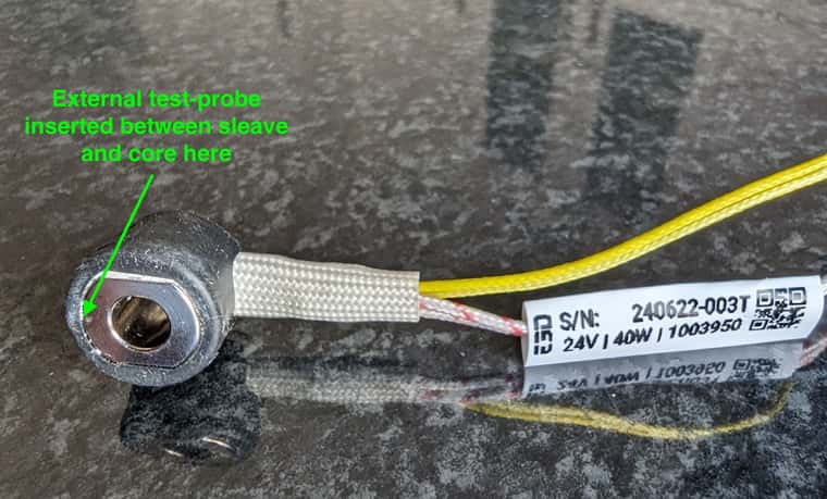
Did some measurements last night. I managed to push my glass-bead temp probe in between the silicone sock with some heat sink compound so it should have a pretty good contact point to the Revo core. I took my hot air station and funnelled hot air over and through the core.
25°C measures about 100 kohm as expected.
99°C measured 5.3 kohm (expected 6,37 kohm)
250°C measured 172 ohm (expected 227,8 ohm) (RRF calc. B4566 C3.492687e-8 )
248°C measured 163 ohm after >5 minutes with heat@250°C. I could also watch that the resistance slowly drifts lower even the temperature is stable or drops a couple of degrees.
262°C measured 133 ohm (RRF calc. B4719 C5.809083e-8 )
All these measurements ware done in one go, I never turend off the heat in between. The resistance drift kind of worries me. I swapped out the multimeter and both measured the same resistance.
I also verified that my measuring probe is dead on the temperatures at 100°C, 200°C and 260°C in my kitchen oven.
So I'm relatively sure something is wrong with the thermistor or E3D used/sourced the wrong ones. They told me "The Thermistor type used on the Creality hotend is a EPCOS 100K B57560G104F." and it has the yellow wrapped wires. So I'll see if I can get a replacement from them. Maybe wait till I can get a 104GT-version instead.
Hmm.. I do have cheap Chinese soldering and hot air station. Have no clue how precise and stable temperatures it can give me. See if I can dig it out and maybe I have a tip I can thread into the revo core or use the hot air while clamping the temp probe to it.
I'll see if I can get some measurements with it.
Redoing my last test last week.
Before turning on the heater for the day I verified it measures room temperature. It shows the same as my measuring probe and bed so it measures correct room temperature (23C).
220 ohm resistor gives 252 degC with the following
M308 S1 P"e0temp" Y"thermistor" L-75 T100000 B4092
Turning on the heater to 100C and my probe shows 81C stable after several minutes. I also added a generous dollop of heat sink compound
like @mrehorstdmd suggested. As it's pressed against the nozzle bottom flat (not the tip) with a wad of paper tissue it should stabilise to something pretty close to the actual nozzle temp.
M308 S1
Sensor 1 type Thermistor using pin e0temp, reading 100.0, last error: sensor open circuit, T:100000.0 B:4092.0 C:0.00e+0 R:4700.0 L:-75 H:0
I just tested a 220 ohm resistor for the Low values and I need L-75 to get a reading of 252 degC.
I'll tried this line now
M308 S1 P"e0temp" Y"thermistor" L-75 T100000 B4092
Room temp was correct
Target temp on Duet 100C resulted in 75C measured by my meter.
Yesterday I verified my own meter on boiling water and it showed 100C so it's good.
@dc42 I could put the whole heater core assy in my oven but don't think I should go above 100C. The connectors might melt 
@dc42 I'm struggling to see how I can do this. I do not have any way to heat up the sensor to a precise true and known temperature. And while the sensors are in use on the Duet I'm not able to measure the resistance by it self.
@dc42 with B4092 it shows the same as the bed which is pretty close to the room temp. 24C.
So might just do the low offset calibration?
Hi,
I have an issue with the sensed temperature on a new replacement E3D heater core. My local shop did not have the core with the regular GT104 so I bought one with the "Creality"-thermistor. According to E3D it's a EPCOS 100K B57560G104F.
Now I have tried what I thought was correct settings and some. I have a measuring probe (glass bead on a meter) pushed against the bottom flat of the nozzle. A thick wad of paper towel is pushing it against the nozzle. The paper also insulates, and I should get a relatively good measurement. To verify my probe I also just measured my bed with the same method and it's spot on after settling.
Setting the Duet 2 to 100 degC with the following configs I get these values:
;M308 S1 P"e0temp" Y"thermistor" T100000 B4725 C7.06e-8 ; measures 92 degC
;M308 S1 P"e0temp" Y"thermistor" T100000 B4092 ; measures 89C
;M308 S1 P"e0temp" Y"thermistor" T100000 B4072 ; measures 88C
;M308 S1 P"e0temp" Y"thermistor" T100000 B3950 ; measures 75C
I believe B4092 is the correct value here but 12C difference at 100C is not good.
Anyone have a suggestion here? My next step is to do a manual calibration on my Duet 2 Ethernet.
I found a 222 ohm resistor but can not find one with more than 10k for the high offset. 10k is about 85C so it's not ideal.
Regards
Stian
Thanks! That sounds sensible.
Thanks. Since you often need less retraction when using PA, I thought to do an initial PA calibration without any retraction. Then calibrate retraction and eventually a new PA calibration to see if it changes in any way.
I usually have retraction set between 0.2 - 0.4, so it's not a lot anyways.
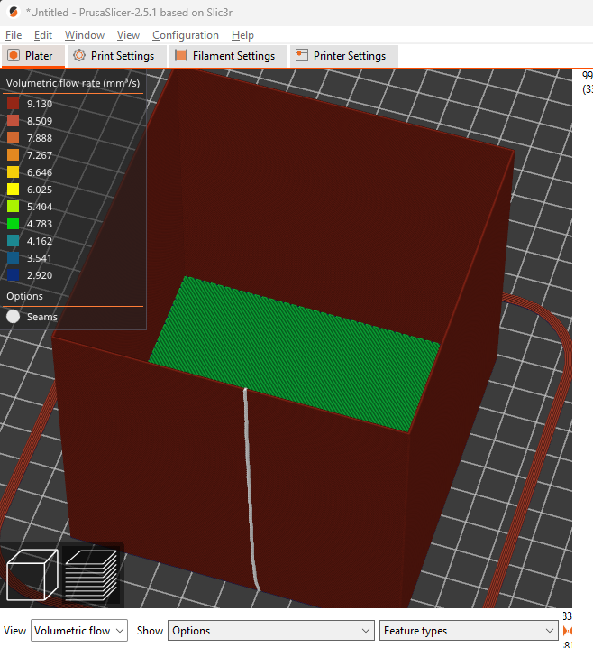
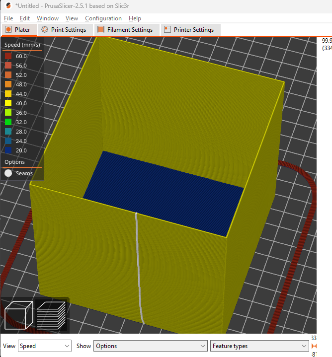
In reality I have a constant speed of 40mm/s in all moves in the test which coincidently gives me a constant flow with only a single wall. At least according to speed and volumetric view in Prusaslicer.