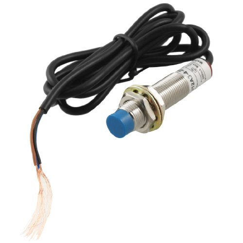
12 volt for inductive Z-probe sensor
-
i got the inductive sensor LJ12A3-4-Z / BX . it needs 12v for operation.

As written in documentation, i put in 10k and 30k resistors.

however, Z-probe connector duetwifi has only +3.3 volts pin and sensor does not work.
From where on the board i can take +12 volts for sensor so that sensor works and board is alive ?
perhaps there are other sensors allowing 10mm distance and +3.3 volts supply?please advise!
-
Are you powering the board with a 12 or 24 VDC supply?
Frederick
-
i got the inductive sensor LJ12A3-4-Z / BX . it needs 12v for operation.
http://3dtoday.ru/upload/blog/a06/797ea2c00b20a65725d6247ac01f7aba.pngAs written in documentation, i put in 10k and 30k resistors.
http://3dtoday.ru/upload/blog/880/797ea2c00b20a65725d6247ac01f7aba.png
however, Z-probe connector duetwifi has only +3.3 volts pin and sensor does not work.
From where on the board i can take +12 volts for sensor so that sensor works and board is alive ?
perhaps there are other sensors allowing 10mm distance and +3.3 volts supply?please advise!
I've the same kind of sensor (setup). I've wired the 12v input to the duet board power supply input (if you are using 12v…) .. any source of 12v will do the job.
Black and signal wire have been connected to one of the endstop connector. I don't remember which one and I don't have access to the printer right nowThe important part is to make sure that your resistences lower the voltage to 3.3v to safely connect it on the endstop connector
-
If it is the NPN variant, you will need a Shottky diode as outlined in the docs:
NPN output normally-open inductive or capacitive sensor
Connect its output wire to the cathode of a diode, and the anode of the diode to the E0 STP pin. Connect the sensor ground wire to a ground pin on the Duet, and the sensor's + power wire to a suitable voltage (typically to VIN because these sensors usually need between 6 and 30V power).The diode should preferably be a small-signal Schottky diode such as BAT43 or BAT85, but a small signal silicon diode such as 1N4148 works for some people.
Select mode 4 in the M558 command. If using firmware 1.15e or earlier, include M574 E0 S0 in config.g to select active low logic level for the Z probe. If using firmware 1.16 or later, include parameter I1 in the M558 command instead
-
my board is powered by 12v