Duet3D Logo

    Duet3D

    • Register
    • Login
    • Search
    • Categories
    • Tags
    • Documentation
    • Order

    Delta printer twisting beginning of print

    Tuning and tweaking
    4
    31
    516
    Loading More Posts
    • Oldest to Newest
    • Newest to Oldest
    • Most Votes
    Reply
    • Reply as topic
    Log in to reply
    This topic has been deleted. Only users with topic management privileges can see it.
    • kjiwa
      kjiwa last edited by kjiwa

      I recently replaced a RAMPS board on my Mini Kossel with a Duet 2 WiFi and have been slowly been dialing in the print settings. I'm at a point where I'm pretty happy with the print quality, but I'm seeing some layer shifting and a small amount of twisting right at the beginning of the print. There are some photos on imgur: https://imgur.com/a/Bo7vGKK.

      The shift occurs at the layer when the letters first appear. Could it be high acceleration or jerk causing this? My acceleration is set to 1000 mm/s^2 and each motor is set to receive 1 A (they are 1.8 deg motors rated for 1.5 A). I used the stepper motor speed worksheet that I found linked on your website and set my print speed to 30 mm/s -- a value that I considered conservative. I also enabled jerk control in my slicer, which I believe is supposed to reduce the jerk, but this setting appeared to have no effect.

      As for the initial twist, I'm not sure what could be causing that. My belts seem to have good tension, and I checked that the towers are straight and have even spacing. It's just the first part of the print that has that twist, so I'm not sure where to begin with this one. I find it strange that the print begins to straighten when the letters are being printed.

      Thank you.

      1 Reply Last reply Reply Quote 0
      • bot
        bot last edited by

        Are you using any mesh compensation or anything? What is in your config.g file?

        *not actually a robot

        1 Reply Last reply Reply Quote 0
        • kjiwa
          kjiwa last edited by

          Hi @bot. Thanks for your response.

          I am not using mesh compensation. Before each print I run a 6-factor automatic calibration. The calibration probes six points around the edge of the bed and also the center point.

          My config.g is here: https://pastebin.com/WgQBag6r.

          1 Reply Last reply Reply Quote 0
          • bot
            bot last edited by

            What are the values given after the calibration is done? Can you perform a calibration and then show the results? IE the tower adjustments or radius adjustments and whatnot.

            *not actually a robot

            1 Reply Last reply Reply Quote 0
            • kjiwa
              kjiwa last edited by

              Here are the results:

              G32
              Calibrated 6 factors using 6 points, deviation before 2.437 after 0.000
              
              M665
              Diagonals 215.000:215.000:215.000, delta radius 107.333, homed height 247.759, bed radius 70.0, X 0.043°, Y -0.594°, Z 0.000°
              
              M666
              Endstop adjustments X0.11 Y0.46 Z-0.58, tilt X0.00% Y0.00%
              
              1 Reply Last reply Reply Quote 0
              • bot
                bot last edited by bot

                I would say that the reason for the "twist" is that the calibration is detecting and correcting for the Y tower being at the wrong angle relative the other two.

                Try setting the parameters manually to the ones that the calibration finds, but don't use the rotational adjustments -- set them to 0. Then see how the same print looks. Is it worse? Better?

                Also, are you sure that your arms are all exactly 215 mm?

                *not actually a robot

                1 Reply Last reply Reply Quote 0
                • kjiwa
                  kjiwa last edited by

                  Thanks for the suggestions. I tried as you stated, to use the calibration results and to set the angular offsets to 0, but this leads to prints that don't adhere to the bed surface in all places. The bed does have a slight tilt to it.

                  As for the diagonal rods, I had measured them each as best as I could from the bearing centers. They each measured very close to 215 mm.

                  1 Reply Last reply Reply Quote 0
                  • bot
                    bot last edited by

                    Ok. Is it 5 factor calibration that ignores the angles of the towers? Can you perform that calibration instead, so that you can determine yourself if your towers are angled instead of the calibration?

                    *not actually a robot

                    1 Reply Last reply Reply Quote 0
                    • kjiwa
                      kjiwa last edited by

                      Thank you @bot. I tried four-factor calibration and confirmed that the tower angular offsets remained 0. Doing this got rid of the twist that I was seeing at the start of my prints, so thank you for suggesting that!

                      Here is how the print looks now: https://imgur.com/a/tJZK2xa. It's much more straight, but you'll notice that there is still some layer shifting occurring where the letters begin and end. The first and last layers also seem to have some additional shift. The last photo in that album shows the effect well.

                      I've tried using different temperature settings to see how that affects the first layer and the overall print smoothness, but those settings didn't seem to help remove the layer shifting.

                      1 Reply Last reply Reply Quote 0
                      • dc42
                        dc42 administrators last edited by

                        That twist has nothing to do with calibration. One or more of your towers is not moving linearly. Are you by any chance using steel-cored belts?

                        Duet WiFi hardware designer and firmware engineer
                        Please do not ask me for Duet support via PM or email, use the forum
                        http://www.escher3d.com, https://miscsolutions.wordpress.com

                        bot 1 Reply Last reply Reply Quote 0
                        • giostark
                          giostark last edited by giostark

                          I'm agree with David. I'm facing the same fate with the universe of delta printer. And I had twist issue too.
                          Before the different rods length (solved with changing all the system) and then geometrical issue (dismounting all the printer 3 times and measuring everything ).
                          The tree main towers were not exactly perpendicular to the bed and at the same distance between each other.
                          Now , I'm modifying the bed resistance for a better radial uniformity and the hot chamber for avoid delamination and warping.
                          EDIT: the TLL-90S is NOT a PRO TOOL , the description is substantially false. An other cheap attempt to steal money.
                          This week I'll receive this (PRO) tool for check all the geometries, TLL-90S (should be accurate enough ). The DXL360s should be good enough too. (i don't know if the DXL360 NON "s" is good enough)
                          alt text
                          But before to check as solved my old 3d I have to accomplish all the proper steps.
                          Unfortunately those issue happen for a reverse approach to the universe of 3D printing. We should've checked at first all this .
                          But , we didn't born already experienced.
                          This guide can help you :
                          https://forum.duet3d.com/assets/uploads/files/1550049854021-tlm-ultimate-calibration-tutorial-1.pdf
                          When it say double check , double check !!!
                          Those problems appear especially printing big parts. Printing small parts in the center of the bed can hide lots of mechanical imperfections.

                          1 Reply Last reply Reply Quote 0
                          • bot
                            bot @dc42 last edited by

                            @dc42 I was never saying that the problem was CAUSED by the calibration. I was using the calibration as a debug tool to see if we can change the print behaviour.

                            Besides, how is the algorithm supposed to determine exactly the amount to rotate the towers? I find that the calibration is good at hinting at these major tower geometry problems, but it's best to sort them out manually rather than let the calibration "fix it."

                            *not actually a robot

                            1 Reply Last reply Reply Quote 0
                            • kjiwa
                              kjiwa last edited by kjiwa

                              @dc42 I do not believe I am using steel-cored belts. When you say the that one of my towers is not moving linearly, are you suggesting that there is some curvature to its movement?

                              In terms of its assembly, I measured the distance between each pair of towers at the top, middle, and bottom, and the horizontal distances were all identical to within 0.5 mm over height of the printer. So this leads me to believe that the towers are fairly parallel to each other. The angular offset should be no more than 0.05 degrees, if even that much.

                              I once again measured each of the diagonal rods and they were all close to 215 mm, but I measured them while the machine was assembled, so my confidence in them being exactly the same is reduced. That said, the rods (and towers) were cut and provided to me by Johann R, who designed the Mini Kossel, so I expect they were measured and cut precisely.

                              I want to note that I didn't have these problems with my RAMPS board, and nothing else about the printer has changed since the upgrade to the Duet 2 WiFi. Here's a sample print from when I still had the RAMPS board on: https://imgur.com/a/L1Hyo4S. I had also printed a 3DBenchy and it came out really nicely.

                              1 Reply Last reply Reply Quote 0
                              • bot
                                bot last edited by

                                Would you be able to provide the settings you used for the delta parameters, steps per mm, etc. for the Ramps/marlin config?

                                *not actually a robot

                                1 Reply Last reply Reply Quote 0
                                • kjiwa
                                  kjiwa last edited by kjiwa

                                  The Marlin config is in my GitHub. A diff from the default settings is here: https://github.com/kjiwa/Marlin/commit/c0d4e67b1c7fc02f868063cb9aff10a0eb38b81c.

                                  With the Marlin firmware I had the tower motors configured with the following values:

                                  • max speed 500 mm/s
                                  • max acceleration 9000 mm/s^2
                                  • default acceleration 3000 mm/s^2
                                  • default jerk 10 mm/s^3

                                  Other than that, geometry and other settings are mostly unchanged between what I had set with the RAMPS board vs what I have set with the Duet.

                                  0 kjiwa committed to kjiwa/Marlin
                                  Configuration for my Mini Kossel.
                                  bot 1 Reply Last reply Reply Quote 0
                                  • bot
                                    bot @kjiwa last edited by

                                    @kjiwa It seems you were using auto calibration in marlin too.

                                    Do you know what delta settings as a result of the auto calibration you were using that gave you acceptable results? Did you ever write them down?

                                    *not actually a robot

                                    1 Reply Last reply Reply Quote 0
                                    • kjiwa
                                      kjiwa last edited by

                                      Unfortunately I did not make a note of those values.

                                      1 Reply Last reply Reply Quote 0
                                      • giostark
                                        giostark last edited by

                                        As "bot"(user 😁 ) , but with less skill , I try to give some help. I have lost so much time back this damn trap of a delta.
                                        I'm agree with him about :

                                        I find that the calibration is good at hinting at these major tower geometry problems, but it's best to sort them out manually rather than let the calibration "fix it."

                                        @kjiwa said in Delta printer twisting beginning of print:

                                        @dc42 I do not believe I am using steel-cored belts. When you say the that one of my towers is not moving linearly, are you suggesting that there is some curvature to its movement?

                                        In terms of its assembly, I measured the distance between each pair of towers at the top, middle, and bottom, and the horizontal distances were all identical to within 0.5 mm over height of the printer. So this leads me to believe that the towers are fairly parallel to each other. The angular offset should be no more than 0.05 degrees, if even that much.

                                        I once again measured each of the diagonal rods and they were all close to 215 mm, but I measured them while the machine was assembled, so my confidence in them being exactly the same is reduced. That said, the rods (and towers) were cut and provided to me by Johann R, who designed the Mini Kossel, so I expect they were measured and cut precisely.

                                        I want to note that I didn't have these problems with my RAMPS board, and nothing else about the printer has changed since the upgrade to the Duet 2 WiFi. Here's a sample print from when I still had the RAMPS board on: https://imgur.com/a/L1Hyo4S. I had also printed a 3DBenchy and it came out really nicely.

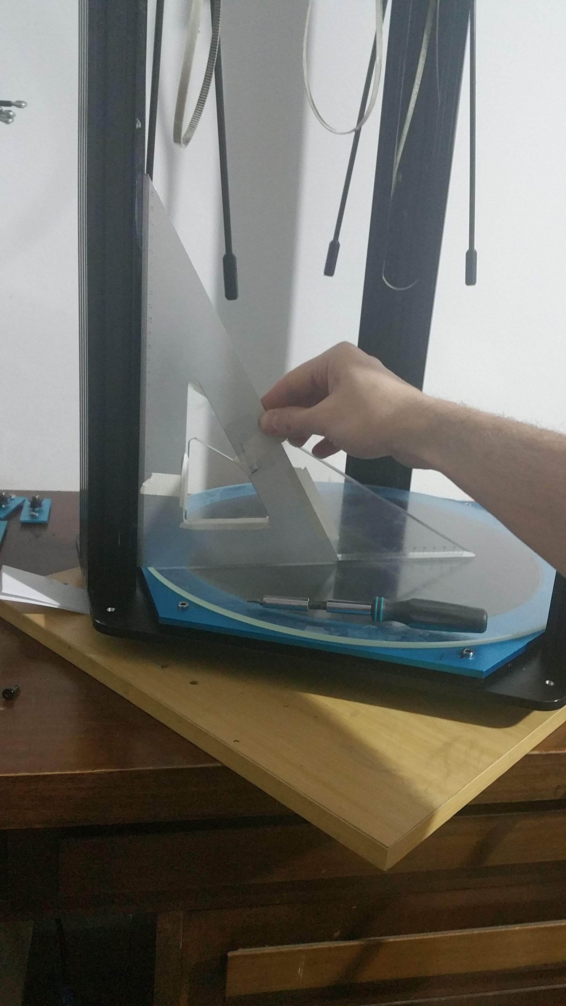
                                        -The tower could have some torsion or be not perpendicular to the bed. If you put a drawing T-square against the bed and the tower , the two sides adhere perfectly? (I before blocked the two T-squares with bi-adhesive against an other square)
                                        20200313_013033.jpg
                                        -I don't know how much difference are allowed in the towers geometries but for the rods must stay in the 0.1mm :
                                        https://duet3d.dozuki.com/Wiki/Calibrating_a_delta_printer
                                        -Did you moved the printer? My delta is so heavy that if the bed is not flat to the ground the tower can flex a little.
                                        -About the belts : the guy tested the GT2 and iron core saw that the last one elongation is 1/3 of the fiberglass core.
                                        https://www.reddit.com/r/3Dprinting/comments/61j9et/i_tested_some_gt2_belts_to_failure_on_a_tensile/dffh799/
                                        http://mark.rehorst.com/misc/corexy/dual belts Z 4kg.jpg
                                        -I would give the full power at the motors in the config.g (1.5A).

                                        If you launch 10 strait calibration , how much big is the deviation between each others? If is too much must be a mechanical trouble. (just because the autocal found different results each time it was performed and it have to recalculate everything) If they are equal +/- 0.01x mm it look like the compensation is working. (ex could be better but is fair enough)
                                        20200306_135136.jpg
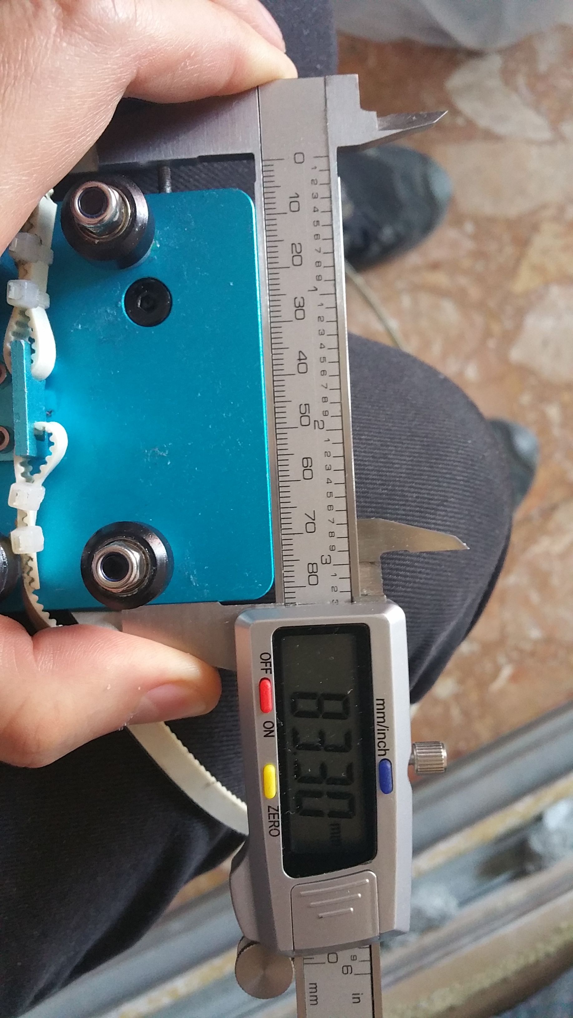
                                        With a digital caliper the cube measure 5cmx5cm or is a rhomboid instead? By the pictures seems irregular.
                                        If there is a mechanical issue the autocal can come even worse that leaving a low factor calibration in the bed.g.
                                        You could try also S8 instead S4 but just avoid the factors that calculate the rods length. BUT you must be sure about the length of the rods!
                                        (the only thing that the autocal make it wrong is calculate the rods length)
                                        I designed a lower parallelepiped (30x3x2 cm) for check the real goodness of the autocal. In small and centered objects the calibration could seems good enough but if you print large object you will find really soon if some issue is still there.

                                        For my calibration.
                                        -endstop all 3 at the same length on the carriage (measured with digital caliper).
                                        20200315_135056.jpg
                                        -I put to zero the M666 in the override.g , save and reboot.
                                        -I calculate the Z height and stored it in the M665 (override.g) , save and reboot and check if it is good (G1 Z0)
                                        -I use the bed.g with 10 out point , 6 internal. The radius as much large you can till the rods are parallel to the towers reach the best results. X3 (tree pass at least). If the build is accurate the second an third pass should be more or less the same.
                                        http://www.escher3d.com/pages/wizards/wizardbed.php
                                        -Now if the geometries are good enough the autocal should work.
                                        -You can refine with the mesh grid.

                                        The process is a chain, all the rings must be right.

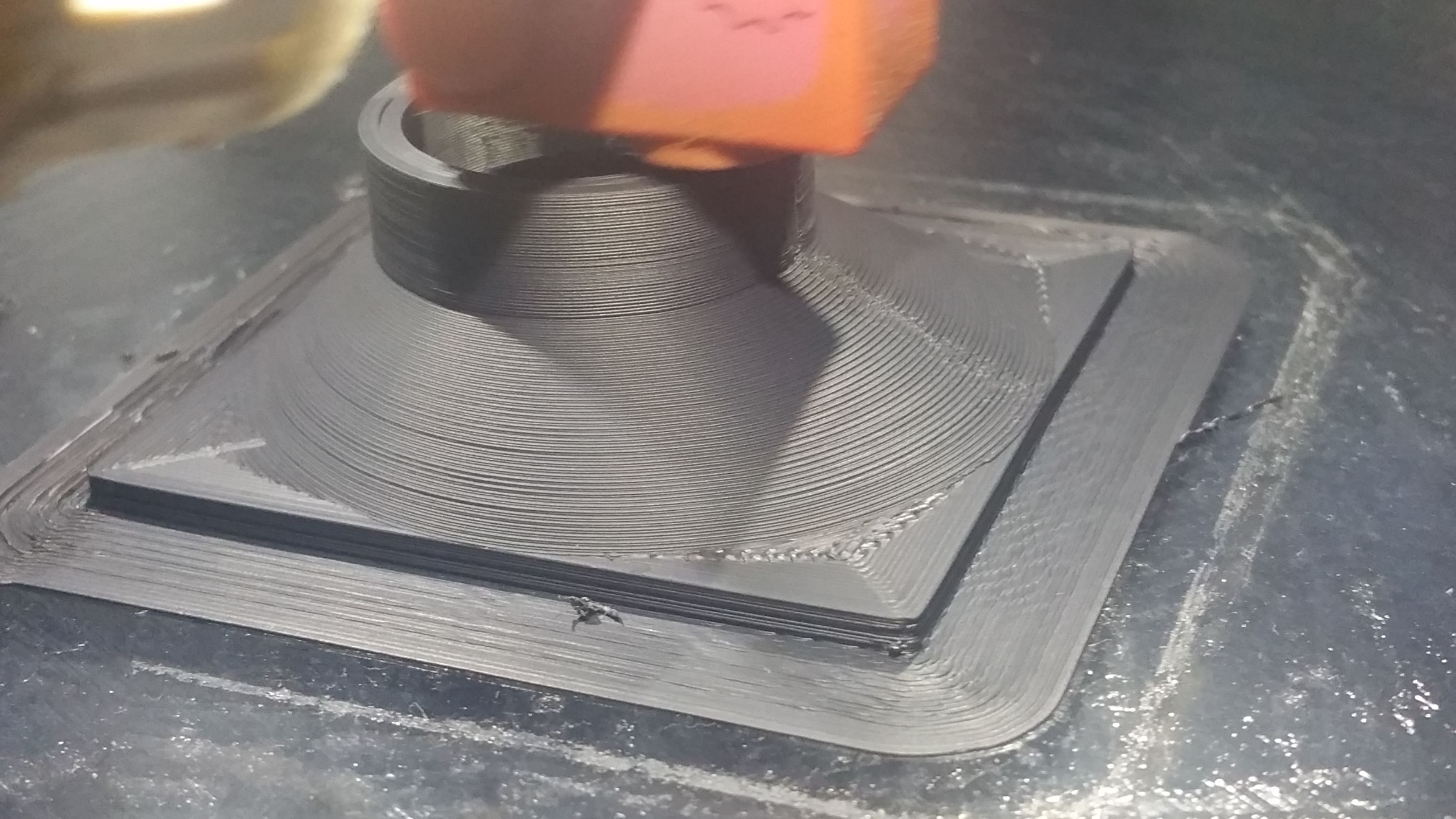
                                        Ah.... this print that look good enough (0.1mm height) is printed with a NOT well calibrated printer. But because in the middle of the bed, all the issue are less noticeable.
                                        ps The ultra squished 1st layer depend on the glue that was irregular (I used a sponge)
                                        Keep us aware of your new discovers 😀

                                        20200305_212113.jpg

                                        1 Reply Last reply Reply Quote 0
                                        • kjiwa
                                          kjiwa last edited by kjiwa

                                          Thanks for the tips @giostark. But as discussed earlier, I'm fairly certain the rod length is accurate, and as I had mentioned, I was able to make good quality prints before when I was using the RAMPS board.

                                          We're at a point where the twist is gone from my prints. It is a small print, but this indicates that my towers are likely straight, and not bowed or highly angled.

                                          The issue I am seeing now is with layer shifting in the calibration cube where the letters begin and end. What could be causing that? There are entire sections of the print that are straight. It's only when there is a change in the object that the layers shift a little bit.

                                          Calibration cube side profile

                                          bot 1 Reply Last reply Reply Quote 0
                                          • bot
                                            bot @kjiwa last edited by

                                            The angle that the firmware was adjusting for was the tower's placement around the circle. IE the Y tower was not evenly spaced compared to the other two.

                                            *not actually a robot

                                            1 Reply Last reply Reply Quote 0
                                            • giostark
                                              giostark last edited by

                                              What happen if you try to print this object on one side of the bed? Maybe close the border?
                                              The shift is there but the right side is more bended of the left one. The center is more narrow of few mm (from the picture).
                                              Please try also to give the full power at the motors.

                                              1 Reply Last reply Reply Quote 0
                                              • giostark
                                                giostark last edited by

                                                OT/
                                                Bot , so this is you !!! 🤗 (just kidding 😳 )
                                                https://www.reddit.com/r/3Dprinting/comments/fohhwo/muahahaha/?utm_source=share&utm_medium=web2x
                                                /OT

                                                1 Reply Last reply Reply Quote 1
                                                • kjiwa
                                                  kjiwa last edited by

                                                  I put some more work into my build and managed to get rid of the twist. My prints are coming out very nicely now. Thank you everyone for the help.

                                                  I believe my issues came from two major areas:

                                                  1. I mentioned earlier that my bed had some tilt to it. I was aware of the tilt, but I was under the impression that the Duet controller could compensate for it. The documentation states that a level bed "isn't essential, because RepRapFirmware can compensate for [it]." Anyway, I redesigned my bed mounting parts and gave the bed a lot more support.

                                                  2. I am using FSRs, but I had not done a great job of calibrating them. This meant that in some cases the nozzle had to depress the bed a lot to generate a reading. When I redesigned the bed mounts, I also used the opportunity to calibrate the FSRs and to make sure that their ambient resistance was in a range where they would be sensitive enough to detect approximately 500g of mass.

                                                  I still have some other settings to dial in now, but at least I can move on from worrying about the straightness of my prints. Thanks again!

                                                  1 Reply Last reply Reply Quote 1
                                                  • kjiwa
                                                    kjiwa last edited by kjiwa

                                                    I was a bit premature in declaring victory. I continue to have issues with layer shifting and autocalibration. At this point I've tried almost everything except replacing the steppers. I've taken everything apart, measured parts to ensure they are sized accurately, and replaced the timing belts, pulleys, and idlers. Still, no improvement to the layer shifting.

                                                    What's really confusing me is why the autocalibration gives me such wild results between runs. Here is the output from the last few invocations of G32:

                                                    Diagonals 215.000:215.000:215.000, delta radius 105.620, homed height 236.757, bed radius 70.0, X 1.482°, Y 0.880°, Z 0.000°
                                                    Diagonals 215.000:215.000:215.000, delta radius 110.722, homed height 237.256, bed radius 70.0, X -14.987°, Y -7.550°, Z 0.000°
                                                    Diagonals 215.000:215.000:215.000, delta radius 106.415, homed height 236.746, bed radius 70.0, X 1.289°, Y 0.492°, Z 0.000°
                                                    Diagonals 215.000:215.000:215.000, delta radius 105.221, homed height 236.595, bed radius 70.0, X -1.524°, Y -0.171°, Z 0.000°
                                                    Diagonals 215.000:215.000:215.000, delta radius 106.281, homed height 236.804, bed radius 70.0, X 1.278°, Y 0.430°, Z 0.000°
                                                    Diagonals 215.000:215.000:215.000, delta radius 106.814, homed height 236.817, bed radius 70.0, X 0.138°, Y 1.348°, Z 0.000°
                                                    Diagonals 215.000:215.000:215.000, delta radius 106.660, homed height 236.546, bed radius 70.0, X 0.512°, Y -0.868°, Z 0.000°
                                                    

                                                    This is just a sample from today. There are times when the control board detects nearly 0 degree offsets, but most of the time it's something like 0.5 degrees. The second one you see is a bit crazy though -- it thinks my build has a nearly -15 degree angle! This is my first ever build, so I may not have done a great job, but I can assure you that nothing about my build is this inaccurate. I have also watched every moving part very closely, but my eye is unable to detect any sort of wobbling or movement.

                                                    @dc42 You mentioned two things that I thought might be the culprit: my belts and the diagonal arms. I tested the arms and they are all the same size (measured as best as I could with my tools). I also wondered if I had abused my belts, so I replaced them in case there was any stretch or wear.

                                                    Any other suggestions? Could it be my linear rails? Or might the motors have some issues?

                                                    dc42 1 Reply Last reply Reply Quote 0
                                                    • kjiwa
                                                      kjiwa last edited by

                                                      Just to close out this thread... since this is not a Duet-related issue I've moved the thread to the deltabot forums on Google Groups: https://groups.google.com/forum/#!msg/deltabot/MKpY_hvHnLE/vij7Q4LOAwAJ.

                                                      Thanks again for all of the suggestions here.

                                                      1 Reply Last reply Reply Quote 0
                                                      • First post
                                                        Last post
                                                      Unless otherwise noted, all forum content is licensed under CC-BY-SA