Hi all ,
i know maybe I should not open this 3d , but to me this was enough singular so I have to report the success of the finding...
The smart effector the last year at one point it started to flicker/dimming . To me was strange some wiring malfunction just because I tried and checked so many time that all was correctly connected ... Frustrated at one point I give up. Then ... a sparkle... Do you want see that the Super Lube (grease) suggested to be used with the magnetic rods have inside some mineral that make it conductive? Nailed. I used some alcohol with cotton fioc to clean between the rods on the smart effector and magically it start to work as expected.
To me this was happened because the hot chamber raised the lube temperatures making it melt a little.
Best posts made by giostark
-
(solved) Flickering LEDs and then dimposted in Smart effector for delta printers
-
RE: WiFi reported error : lost connection auto reconnectingposted in Using Duet Controllers
The board is 2m in strait line in the same room of the router.
"Intereference" ... maybe the fan (120mm) over the board? But is the first time happen and the fan is always the same as always.
(I swear ones finished the enclosure I'll fix that mess of wires )
)

- WiFi - Network state is active WiFi module is connected to access point Failed messages: pending 0, notready 0, noresp 0 WiFi firmware version 1.26 WiFi MAC address 68:c6:3a:cd:1e:cf WiFi Vcc 3.31, reset reason Power up WiFi flash size 4194304, free heap 25936 WiFi IP address 192.168.1.4 WiFi signal strength -48dBm, mode 802.11n, reconnections 0, sleep mode modem Clock register 00002002 Socket states: 0 0 0 0 0 0 0 0 -
[solved] Several Newbie questions - porting fron RRF2 to RRF3posted in Firmware installation
Hi all,
Hope some good soul can give me some advice . Finally I'm here on the RRF3 too. The 2.05.1 produce some strange errors. If I try to use the micro-steps suddenly the heater report fault. The height come wrong and the printer restart to print too hight or too low. Anyway lets go on..
I have installed the RRF 3.01.rc12 . Paneldue 7i updated at 1.24. Web control to 2.1.7. DuetWIFI rev 1.02
Delta printer as 3D printer.
I tried to dig in guides and https://www.reprap.org/wiki/G-code but I still miss to many stuffs.
https://duet3d.dozuki.com/Wiki/RepRapFirmware_3_overview#Section_Summary_of_what_you_need_to_do_to_convert_your_configuration_and_other_files1)EDIT:
Where I can found the real PIN names of the board?(schema or list). I thought they could be the names of the board diagram but they are not.Ex: for bed thermistor I expected "thermistor0" instead seems to be "bedtemp". So for sure I copy-pasted wrong names everywhere.
Ok I was blind/fuse, found the list...hemm...I'll try to read better.2a)EDIT:
The PanelDue 7i didn't show any temp despite the webcontrol does (also if wrong values) . No nozzle heater , no bed heater , no chamber heater , no extra heater added.
Reading is a good practice: https://github.com/dc42/RepRapFirmware/blob/v3-dev/WHATS_NEW_RRF3.md
Added to the M575 P1 S1 B57600 to config.g and the IAP.bin make the PaneDue work properly., Before was stuck on "connecting".2b) EDIT:
I added a 4rth thermistor (as shown in the config.g) . How I can map it for RRF3?
Reading the correct PIN name and M308 and M950 functions make me to insert the right value.2c) EDIT:
The thermistors , except for the bed that is right, reports wrong values also if old setting are used. 100degree instead near 25.
Basically the wrong setting leave report wrong values.
Now this code work good for the heaters all.; HEATERS : M308 S0 P"bed_temp" Y"thermistor" A"Bed" T100000 B3950 ; define bed temperature sensor M950 H0 C"bed_heat" T0 ; heater 0 uses the bed_heat pin, sensor 0 M308 S1 P"e0_temp" Y"thermistor" A"Nozzle" T100000 B4725 C7.06e-8 R4700; define E0 temperature sensor for nozzle M950 H1 C"e0_heat" T1 ; heater 1 uses the e0_heat pin and sensor 1 M308 S2 P"e1_temp" Y"thermistor" A"H_C_Resistor" T100000 B4725 C7.06e-8 R4700 ; configure sensor 2 as thermistor on pin e1_temp for hot chamber M950 H2 C"e1_heat" T2 ; heater 2 uses the e1_heat pin and sensor 2resistence M308 S3 P"e2temp" Y"thermistor" A"Enclosure" T10000 ; configure sensor 3 as thermistor on pin exp.35 for enclosure ;M950 P3 P"exp.heater3" T3; sensor 3 uses the exp.35 pin and sensor 3 M140 H0 ; the bed heater is heater 0 M141 H2 ; heater 2 is the chamber heater3)EDIT:
Fans I would reach: FAN0 (connection on the schema) is for the nozzle in thermostatic mode. FAN1(connection on the schema) is for cooling the printed part and should be used by the slicer or manually controlled. FAN2 (connection on the schema) I would leave it manually for the hot chamber with a minimum of 30% on.
As for before with the proper PIN names all came to work.4)EDIT:
Endstop? If I try to home nothing move.
They work fine:; Endstops M574 X2 S1 P"xstop" ; Set active high endstops M574 Y2 S1 P"ystop" M574 Z2 S1 P"zstop"5)EDIT:
Smart effector? I copy pasted , but of course I don't know if is right.
It seems to work.6)EDIT:
Filament sensor? Still as above how to map it?
No error report but still to be tested; Filament Sensor - Add the following to config file anywhere before the M501 command M591 D0 P1 C"e0_stop" R20 S1; configure extruder drive 0 to use E1 endstop (C4) with 20% tolerance , new extruder settings for filament sensor7)EDIT:
The TOOL section have the fan reverted (nozzle - cooling part) but now I don know if this is still necessary because the new mapping system. In the case how to do that again?
The exchange between the nozzle fan and tool fan is still valid.THANKS TO ANYONE WILL CONTRIBUTE

My config.g:
Config.g ; General preferences G21 ; Work in millimetres G90 ; Send absolute coordinates... M83 ; ...but relative extruder moves M575 P1 S1 B57600; enable panel due to connect properly M665 L400.320:400.310:400.310 R164.588 H508.538 B165.0 X-0.087 Y-0.059 Z0.000; Set diagonal rod length, delta radius, printable radius and homed - M666 X0.00 Y0.0 Z0.0 A0.00 B0.00; Put your endstop adjustments here, or let auto calibration find them ; old setting M666 X0.45 Y0.40 Z-0.25 A0.00 B0.00; ; Network M550 PTEVO Little Monster ; Set machine name M552 S1 G4 P1000 M587 S"Vodafone-casa24" P"xxxxxxxxx" M586 P0 S1 ; Enable HTTP M586 P1 S0 ; Disable FTP M586 P2 S0 ; Disable Telnet ; Motors 0.9 degree M569 P0 S1 ; Drive 0 goes forwards M569 P1 S1 ; Drive 1 goes forwards M569 P2 S1 ; Drive 2 goes forwards M569 P3 S0 ; Drive 3 goes forwards M350 X16 Y16 Z16 E16 I1 ; Configure microstepping with interpolation M92 X160 Y160 Z160 E920 ; Set steps per mm M566 X1200 Y1200 Z1200 E1200 ; Set maximum instantaneous speed changes (mm/min) M203 X18000 Y18000 Z18000 E1200 ; Set maximum speeds (mm/min) M201 X1000 Y1000 Z1000 E1000 ; Set accelerations (mm/s^2) M906 X1700 Y1700 Z1700 E1700 I60 ; Set motor currents (mA) and motor idle factor in per cent.I100 is idle 100% power motor. By def 1700 for axis and 1500 for Extruder for standard motors. For 0.9 motors use 1700 for 3 axis and 1700 for extruder (the motors are the same). ;M84 S30 ; Set idle timeout ; Axis Limits M208 Z0 S1 ; Set minimum Z ; Endstops M574 X2 S1 P"xstop" ; Set active high endstops M574 Y2 S1 P"ystop" M574 Z2 S1 P"zstop" ; Z-Probe M307 H3 A-1 C-1 D-1 ; Disable heater on PWM channel for BLTouch M558 P8 C"^zprobe.in+zprobe.mod" H5 F1200 T6000 A5 R0.4 ; P9 for BLTouch, dive height 5mm=H5 (can be less if the error margin is less than 0.2 , ex H3), probe at 100mm/min, travel 6000mm/min, up to 5 probes, pause 0.1s ; M558 P8 R0.4 F1200 for smart effector G31 P100 X0 Y0 Z-0.05 ; Set Z probe trigger value, offset and trigger height. The higher the Z value, the closer the bed will get to the nozzle. G31 X0 Y20 Z1.150 P25 for BLT. - G31 P100 X0 Y0 Z-0.1 for SMART. M557 R165 S15 ; Define mesh grid ; HEATERS : M308 S0 P"bed_temp" Y"thermistor" A"Bed" T100000 B3950 ; define bed temperature sensor M950 H0 C"bed_heat" T0 ; heater 0 uses the bed_heat pin, sensor 0 M308 S1 P"e0_temp" Y"thermistor" A"Nozzle" T100000 B4725 C7.06e-8 R4700; define E0 temperature sensor for nozzle M950 H1 C"e0_heat" T1 ; heater 1 uses the e0_heat pin and sensor 1 M308 S2 P"e1_temp" Y"thermistor" A"H_C_Resistor" T100000 B4725 C7.06e-8 R4700 ; configure sensor 2 as thermistor on pin e1_temp for hot chamber M950 H2 C"e1_heat" T2 ; heater 2 uses the e1_heat pin and sensor 2resistence M308 S3 P"e2temp" Y"thermistor" A"Enclosure" T10000 ; configure sensor 3 as thermistor on pin exp.35 for enclosure ;M950 P3 P"exp.heater3" T3; sensor 3 uses the exp.35 pin and sensor 3 M140 H0 ; the bed heater is heater 0 M141 H2 ; heater 2 is the chamber heater M141 H2 ; heater 2 is the chamber heater ; Tools M563 P0 D0 H1 F1 S"Nozzle"; Define tool 0 L'F1 inverte la ventola del tool e le ventole di raffreddamento. cosi' quando sposto il cursore del tool varia correttamente l'intensita' della ventola del nozzle. (prima invece cambiavano le ventole di raffreddamento) G10 P0 X0 Y0 Z0 ; Set tool 0 axis offsets G10 P0 R0 S0 ; Set initial tool 0 active and standby temperatures to 0C ; Fans M950 F0 C"fan0" T0 M106 P0 S1 X1 H1 T45 ; Set fan 0 value, PWM signal inversion and frequency. Thermostatic control is turned off - 0.3 is 30% M950 F1 C"fan1" T1 M106 P1 S0 H-1 ; M106 P1 S0 I0 F500 H-1 ; Set fan 1 value, PWM signal inversion and frequency. Thermostatic control is turned off M950 F2 C"fan2" T2 M106 P2 S0 H-1 ; Set fan 0 value, PWM signal inversion and frequency. Thermostatic control is turned off - 0.3 is 30% ; Automatic power saving M911 S10 R11 P"M913 X0 Y0 G91 M83 G1 Z3 E-5 F1000" ; Set voltage thresholds and actions to run on power loss ; Custom settings ;M591 D0 C3 P2 E6.0 ;old extruder settings ; Filament Sensor - Add the following to config file anywhere before the M501 command M591 D0 P1 C"e0_stop" R20 S1; configure extruder drive 0 to use E1 endstop (C4) with 20% tolerance , new extruder settings for filament sensor ; Miscellaneous M501 ; Load saved parameters from non-volatile memory ; deployprobe.g ; called to deploy a physical Z probe ; generated by RepRapFirmware Configuration Tool on Sat Jul 07 2018 15:37:48 GMT-0700 (Pacific Daylight Time) M280 P3 S10 I1 M280 P3 S90 I1 -
RE: Delta printer twisting beginning of printposted in Tuning and tweaking
OT/
Bot , so this is you !!! (just kidding
  )
)
https://www.reddit.com/r/3Dprinting/comments/fohhwo/muahahaha/?utm_source=share&utm_medium=web2x
/OT -
RE: Error: Temperature reading fault on heater 0posted in Duet Hardware and wiring
I found this that should be where you lies at this point:
https://duet3d.dozuki.com/Wiki/Connector_and_spare_part_numbers#Section_VSSA_fuse
But right now I'm not capable enough to give suggestions
-
RE: Smart Effector setup issuesposted in Smart effector for delta printers
@incidrthreat
Hi, I have a delta so I'll try to be useful...
The error that is blocking your right probing is this , in "config.g":
Rnnn : Radius to probeM557 R90 S20 ; define mesh gridThe R parameter MUST be bigger that the value (radius) you set in http://www.escher3d.com/pages/wizards/wizardbed.php bed generator.
Now , as you wrote , they are coincident so they come skipped.
Your radius is 140 so try M557 R120 S20 instead.Then, cosmetic stuff... I suggest you to erase the G31 line in the config-override and work for the zprobe in config.g for don't make splitted code. And leave geometrical and other auto-calibration in the override.
1)In config-override (remove this line and work in config.g):
; Z probe parameters
G31 K0 P500 X0.0 Y0.0 Z-0.31
-What is in G1 "K0" for? in the wiky https://www.reprap.org/wiki/G-code#G31:Set_or_Report_Current_Probe_status it is not mentioned.
I dont know if this can generate errors somewhere. Remove it.
-Try to set "Z-0.1" till you are not certain that all work as it should. Then you'll refine the stuffs.
-P500 . For the smart-effector this line is suggested G31 P100 X0 Y0 Z-0.1. (look at commissioning)
https://duet3d.dozuki.com/Wiki/Smart_effector_and_carriage_adapters_for_delta_printer
https://forum.duet3d.com/topic/16758/g31-trigger-value-what-is-it-good-for?=16413455686242)In config.g ,despite it come bypassed by the config-override.g ,change the Z from 5 to Z-0.1. 5 mean to fly too hight for the head.
G31 P500 X0 Y0 Z5For the smart-effector this must be "P8" not "P5"...
M558 P5 R0.4 C"zprobe.in+zprobe.mod"For the axis limit set a negative value so that if your Z0 is too high (for some reason) and with babystep you have to go really close the bed , you'll can. Set it ex at Z-0.3.
; Axis Limits
M208 Z0 S1                                          ; set minimum Z
After you made those change to the code:
-power off , power on the printer.
-home (G28)
-run a single probe (G30). (it will be slow)
-keep the right height and write it in the override.g M666 H parameter.
-restart the printer
-run at least 3xG32
-in console type M665 for read the actual value and copy ONLY the R in the ovverride.g. (and leave the M666 to 0 for all the items)
In this way you will leave to the auto-calibration the job to recalculate the other parameters. In my experience if you put too much manual settings and they are not perfect , the result come even worse.
So basically for the M665 you can add manually : rod length , radius (after at least 3 calibration) , height.It's late here in Italy... I dont' know if there are more errors in your files... but I'll collapse .... try those change and let us know
-
RE: [solved] Several Newbie questions - porting fron RRF2 to RRF3posted in Firmware installation
To read deeply and with more attention unveil lots of good stuffs.
-
RE: Delta printer twisting beginning of printposted in Tuning and tweaking
Ok,
Also I suggest you to verify those alignments.
Those must be at the same equal distance.
Doing this I reached that the X and Y of M665 are gone from several decimal to some cents.
In those trap we must gain as much precision everywhere
In my case for obtain the more possible equal distance , I was not able to keep the tower aligned with the top frame.


-
RE: Thermistor's shows 2000°C ( Slolved )posted in Duet Hardware and wiring
Ok Thomas.
Deck is right , you are using the v2 firmware with v3 settings.
For upgrade the firmware from 2 to 3 you have to make before 2.xx.x>3.0 then 3.0>3.1.1
If you have the panel due don't forghet to add this line on top :
M575 P1 S1 B57600; enable panel due to connect properly
Here all the info:
https://duet3d.dozuki.com/Wiki/RepRapFirmware_3_overview#Section_Summary_of_what_you_need_to_do_to_convert_your_configuration_and_other_filesps:
damn ctrl+shift+enter had tripled the post... -
RE: ABS print help first time at ABSposted in General Discussion
After 2 years of digging with abs and than ASA i build up some "experience" and I try to share it.
Unfortunately abs , like ASA, are beast to deal with. They have "a lot" of material retraction depending on temperature. (ApolloX have a little less bending but is expensive)
So , start to become far more important all the temps on the field.
Bed adhesion must be strong. Really strong and despite the part didn't detach from the bed the part could cum still a little bended.
This depend also by the bed temp. And are two different banding causes , bed and volume air.
Lots of guides tell you the the bed temp should be close the class transition (100degree) but in my experience 100/110degree are too hight and the first 5mm of the part come always severely bended (big prints). I discovered that a good adhesion and 80/85 degree (for all the surface of the bed - used thermo-camera and modded bed resistor for achieve this) produce a better result. Still no perfect , but ok till the hot chamber will be finished .
Yes, because you probably will need an hot chamber (the enclosure alone could not be enough). I can't say the exact temp you need to reach inside because depend also by your specific material.
By your pictures seems that the bed temp is too hight (could be confirmed also by the guide in the bottom link).
https://support.3dverkstan.se/article/23-a-visual-ultimaker-troubleshooting-guide#wallcavein
And...I found useful print with "draft". If you modify this setting properly (Cura slicer) the heat of the bed come a little less on the part avoiding too much different from the top layers and the first.
With small parts , "brim" could be sufficient.
Also, air on the part must be avoided (of course not if the part is really small). So check if your tool fan don't create turbulence.
Because of this the good suggestion of mrehorstdmd of print more part at ones could be useful.
By the first pictures seems not even regular the two corners (one convex and the other concave) and this is not because the temps but geometric calibration.
All the parts have their specific setting and attention required. Some doesn't need particular work on but others are really tricky.
Especially block and infill at 100% generate lots of tensions.
If you want print only one small part Maybe you could try to print the cube test with draft and the part fan on at low percentage.
With low object (till 1cm or so), there is no problem , but when the part rise the tensions become stressful.
Also the design of the part will make a good part in the full equilibrium of the print.Here there are good suggestions that can help you to found you specific settings.
https://support.3dverkstan.se/article/23-a-visual-ultimaker-troubleshooting-guide
Latest posts made by giostark
-
RE: End Stop for high temperature coreXY - suggestion/adviseposted in Duet Hardware and wiring
@dc42
Thanks David!
The idea would be stay at max 100d in the enclosure. This should be enough for the material I'll go to print . But to have some margin can be useful , for safety and maybe upgrade. The link is very appreciate !
For peek I read that the enclosure should stay from 70 to 150d . I cannot effort the 150 target (because all the hardware limitation) but maybe a compromise is achievable and enough at the end.
I'm not in hurry to finish the printer so I would like build something that have sense and is coherent with all its parts.
I'll keep you informed on the progression of the selection and installation !
Cheer !!! -
End Stop for high temperature coreXY - suggestion/adviseposted in Duet Hardware and wiring
Hellooooooo ! Dear beauty of a community
...
Im building (as reported lots of time ago) this "fine" piece of printer.
I'll open the proper 3D in the right section with all the spec , mods , developments etc etc.
The electronic are all Duet . With some structural customization , but the project is this one https://railcore.dozuki.com/c/RailCore_II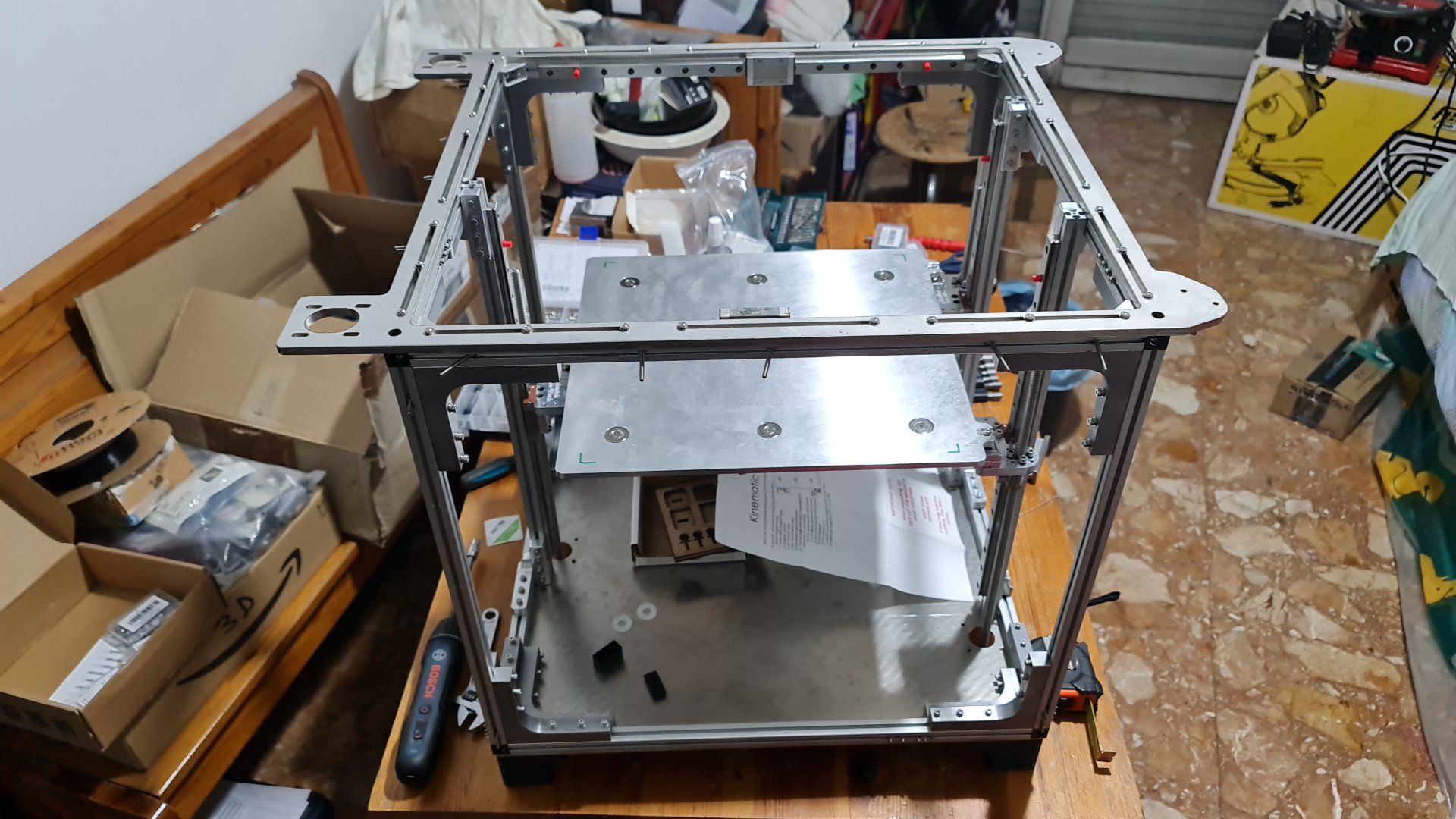
Now:
This thing would be designed for high temp material . The rails are Misumi for high temp (rated 140deg) . Rest is metal.
The problem I realized , the end stop ! Rest intended that I have to build their support but , which ones ?
The ones I found may resist and stay operational till 85 degree . But If I'll print policarbonate or peek this will be not enough (maybe) or too close the rated temp.
Do you have any suggestion on the right model suited for the task ? And maybe also where to buy them.
I'll need 7 of them. 2 for X , 2 for Y and 3 for Z .
Thanksss ! -
RE: use M552 to abandon the current connectionposted in General Discussion
@droftarts
Thanks Ian !
I wrote to Phaedrux and asked him to do this . (I wrongly supposed him would ask you that because instead you were faster !)
This community is very great . I really really like it , so I hope to be helpful in future.
Cheers ! -
RE: use M552 to abandon the current connectionposted in General Discussion
@jay_s_uk
Eh...you nailed it Thanks.
I don't understand why my brain did not considered this option. Damn.
Anyway would be useful for other noob to add this line in the guide right under the " Use M587 to add a WiFi..." :"If you have already store the connection , disable the line M587 with the wifi data." (or something like that)
This is the standard setup, with the Duet 3 Mini 5+ WiFi (in standalone mode) or Duet 2 WiFi connecting to your network through a WiFi access point/router. This is covered in the Getting Connected guide. Briefly: Connect to Duet, via USB and serial terminal, or via console if already connected to network. Use M587 to add a WiFi host network to the remembered list of networks. To set a static IP address, use the 'I' parameter in your M587 command. If you leave this out, the Duet IP address will be set by the router, using DHCP. Use M552 S1 to turn on networking, and connect. You can specify the host network to connect to using the 'P' parameter, so long as the host network has already been stored using M587. Note: the IP addresses in the following diagram are an example of how a network may be configured. Your network may use different IP addresses and ranges. -
use M552 to abandon the current connectionposted in General Discussion
Hi ALL !!!
Finally back in business
Probably after an update is popped out this error:Error in start-up file macro line 29: use M552 to abandon the current connection attempt before using this commandMy network section was always like this with no errors:
; Network
M550 PDelta-Printer ; Set machine name
M552 S1
;G4 P1000 (old setting to create a delay from activation wifi and check the wifi name saved previously)
M587 S"*****" P"*****" I*****
M586 P0 S1 ; Enable HTTP/HTTPs
M586 P1 S0 ; Disable FTP
M586 P2 S0 ; Disable Telnet
I tried to enable or disable the G4 P1000 but do not change a thing.
I would say that the error rise two update ago.config.g
I had a look here : https://docs.duet3d.com/User_manual/Machine_configuration/Networking
And seems fine the configuration.
Any clue ? -
(solved) Flickering LEDs and then dimposted in Smart effector for delta printers
Hi all ,
i know maybe I should not open this 3d , but to me this was enough singular so I have to report the success of the finding...
The smart effector the last year at one point it started to flicker/dimming . To me was strange some wiring malfunction just because I tried and checked so many time that all was correctly connected ... Frustrated at one point I give up. Then ... a sparkle... Do you want see that the Super Lube (grease) suggested to be used with the magnetic rods have inside some mineral that make it conductive? Nailed. I used some alcohol with cotton fioc to clean between the rods on the smart effector and magically it start to work as expected.
To me this was happened because the hot chamber raised the lube temperatures making it melt a little. -
RE: Flickering LEDs and then dimposted in Smart effector for delta printers
@Phaedrux said in Flickering LEDs and then dim:
@RogerPodacter May be best to start a new thread.
Hi folks ! I'm back on a CNC for make some part for a new 3D printer... so now i'm a little for other stuffs.
Today I start a print and this happen to me exactly in the same way.
I should open a new 3D but the things are exactly the same.
Tomorrow I'll check the connections and the suggested solution by David and report something. -
RE: Strange Blobbing on Layer Changeposted in Tuning and tweaking
@davidewen
On the Bondtech BMG I have settled E1200. Tie well the screw otherwise the gears will dent the wire. -
RE: Strange Blobbing on Layer Changeposted in Tuning and tweaking
@davidewen
Yep the Z in M566 could be higher. Right now I have just a delta printer and settled 800 on all 3 axis.
You have 900 on x and y. Why so slow on z with just 60?
David suggest the default as 600 in this post:
https://forum.duet3d.com/topic/310/m566-what-s-a-good-number
But someone use even 1200.Please if you found the solution replay here so that will be useful to us all
ps:
I have to learn to check before the config.g and then the slicer , damn. Here the phaedrux's skill was evident!
My advice still remain good for refinement
-
RE: Z seam blobs, pause at layer changeposted in Tuning and tweaking
@Phaedrux
Yo Phaedrux!
He posted the same thing here (link) and I tried to answer him... let see if he will solve the problem:
https://forum.duet3d.com/topic/14846/strange-blobbing-on-layer-change/32ps:
i'm restoring a CNC for build some part for the full metal CoreXY high temp I'm assembling... That will be a very fine piece of hardware
Soon as possible I'll post stuffs