Printer Power Question
-
Edit: added image below. I think the wiring with the Duet is not going to work, since Power_ON only ground 5V and does not output it, if I understood correctly.

-
The general flow makes sense. I believe the Diodes will work. There will be some 'discovered' things as you build it of course...
-
@Danal revisited the schematic. I'm confident it should work the following way, requiring a mosfet for the RPi to switch the relay to ground. PS_ON is able to easily sink 12V so it should be fine.

-
The Duet output is no different that the Pi GPIO: Both are a pin on a micro CPU that can only source/sink a few mA at best and at 3.3V. So if you need a mosfet on one, you need it on the other.
Also, I don't see how that switch is going to toggle with repeated pushes.
Were it me, I would:
- Not mix 5V and 3.3V. Control the SSR with 3.3.
- Use two separate push-button switches, one labeled ON and one labeled OFF
- This does imply a 3.3V standby power from somewhere.
There is a lot more to it than that... I'll see if I can post more detail later.
-
The momentary switch is only to start the relay for the 24V power supply for few seconds to provide power to the Duet. Duet then takes over with powering the relay/itself using M80/M81.
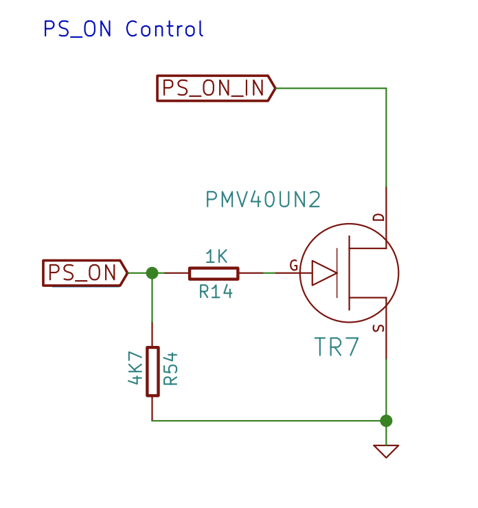
As I understood it M80 will switch PS_ON pin to ground (via a PMV40UN2 mosfet) (source: https://reprap.org/forum/read.php?416,680735). Meaning I will have to provide +V to it. On the other hand, GPIO pin on RPi outputs +V and cannot sink current. Or am I mistaken?
Thanks for your help.
-
@schmluka said in Printer Power Question:
The momentary switch is only to start the relay for the 24V power supply for few seconds to provide power to the Duet. Duet then takes over with powering the relay/itself using M80/M81.
As I understood it M80 will switch PS_ON pin to ground (via a PMV40UN2 mosfet) (source: https://reprap.org/forum/read.php?416,680735). Meaning I will have to provide +V to it. On the other hand, GPIO pin on RPi outputs +V and cannot sink current. Or am I mistaken?
Thanks for your help.
RPI can source or sink, as I understand, at 3.3V, and only about 4mA. Same for Duet. The nice thing is, if you forcibly crowbar them to ground, that is OK. They have their own current limiting resistor.
So that is an "ON" button, cannot be used to power off? That should work fine, assuming the RPI is present and outputting 3.3V.
-
@Danal thanks for taking the time.
I think I will leave the RPi control away for now to get a simpler system. Yes, push button is ON only.
I will provide the Duet 2 Wifi with 5V from always on 5/12V PSU.
I will run 12V to one end of relay, the other end goes (1) through push button to ground and (2) to PS_ON pin.I prefer 12V to 5V (or 3.3V) for higher signal stability since Push button is wired ~1 meter away of the Relay, and PS_ON should manage the 12V input as far as I read. Still confused about how the PS_ON actually works, tho.
If you can, please do lecture me on PS_ON an its correct usage

-
@schmluka said in Printer Power Question:
If you can, please do lecture me on PS_ON an its correct usage
Hmmm... I'm not an expert on that pin setup. Let me look at the schematic a little.
-
@Danal looks to me as if PS_ON switches PS_ON_IN via mosfet to ground. I think using 12V should not be a problem.

-
For anyone interested: the second drawing/image works. However, the Ground Pin on Duet 2 Wifi next to PS_ON had to be connected to power supply ground. I am, however, unsure why that's the case.