Choosing a Z axis style
-
Now that I got an idea how I want the Z axis to be constructed, I thought a bit about mounting the bed to the bed frame.
I want kinematic mount (like what @mrehorstdmd did on his printers), including PTFE blocks for thermal decoupling. However, I do not have access to a mill or basically any machine tools except a drill press. This made one of the three reference points (the one with the groove, only allowing lateral movement in one direction) a bit non-obvious.
One idea I came up with is using 10x10x1mm square tubing, as that's something I can easily buy locally. Those are shown in blue in the following images.
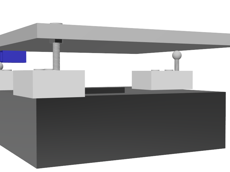
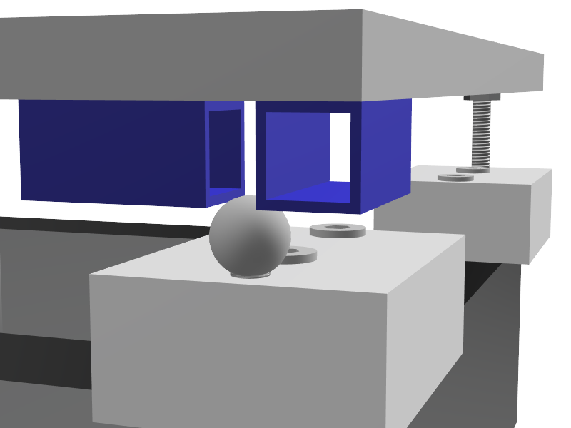
(Springs are still missing)After I finished that sketch, I realized that two M4 or M5 nuts (either hex or square), with a well-chosen distance between them, would probably serve the same purpose, but with less height being lost.
If someone has another idea, using easily availble standard parts, I'm all ears
")
-
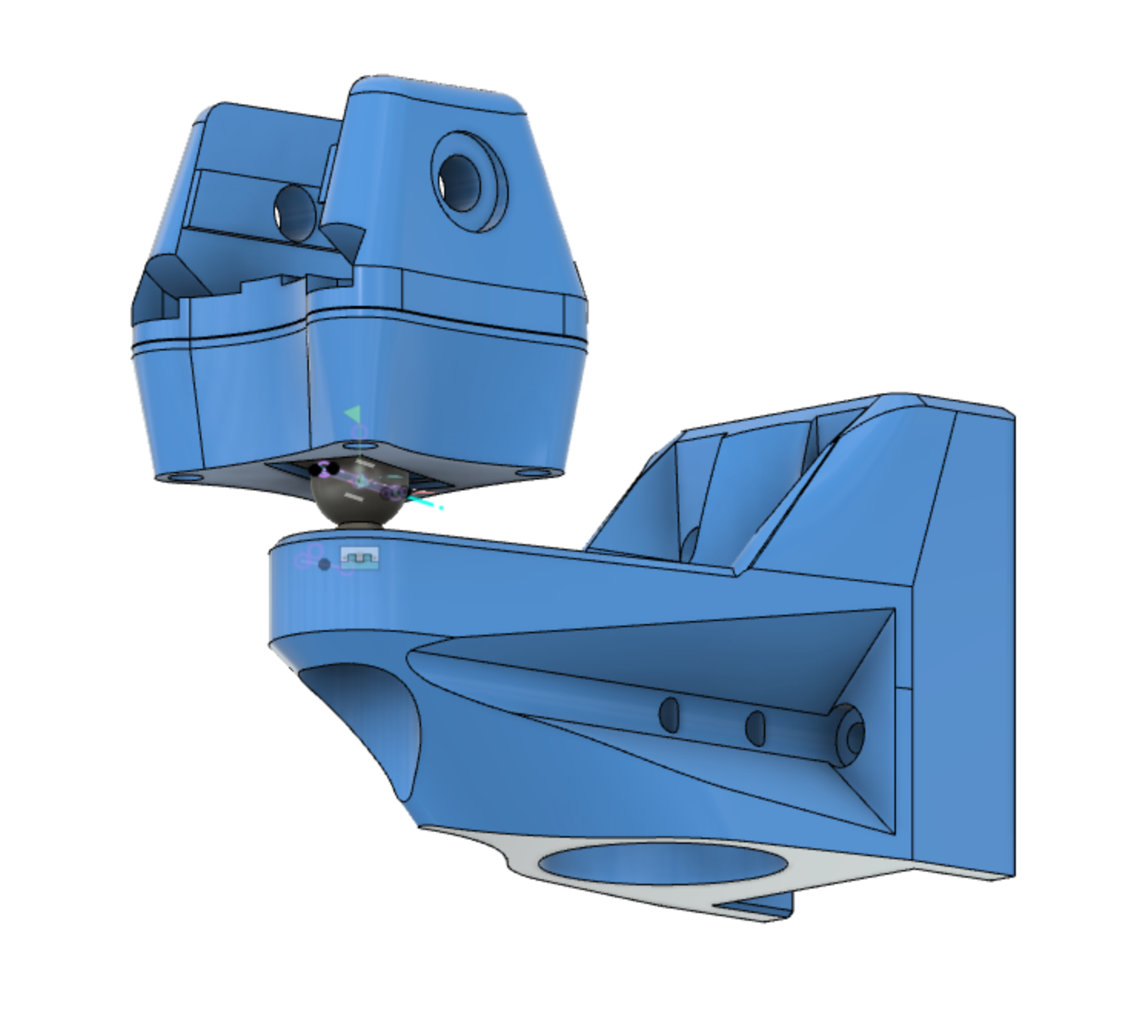
I'm currently working on a 3-lead kinematic Z axis for my CoreXY. I'm using short pieces of 2020 extrusion as thermal isolation between the bed (a repurposed Railcore 300ZL aluminum bed) and the printed mounts. Some blocks of drilled PTFE would work even better if there still ends up being too much conduction through the extrusion. I'm using neodymium magnets + magnetic ball joints for the 2, 1, and 0 linear dof mounts.

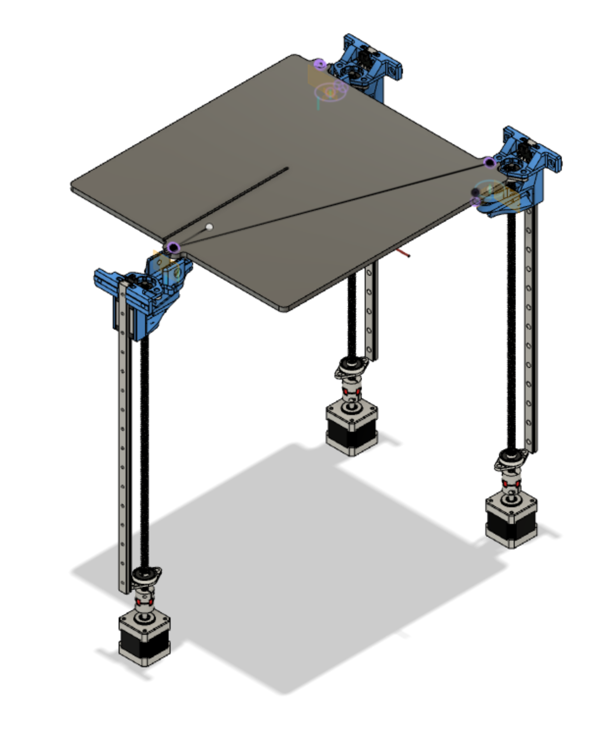
Still waiting for a few more parts to come in before I put it on the printer. By eliminating a rigid under-frame for the bed, I'm hoping I will be able to avoid some of the wear problems that can arise from having over-constrained Z rails, while retaining enough stability for reliable prints. In principle, it should also be possible to use the kinematic mount to help align the rails, by coating the magnets with some dry-erase marker, running the bed up and down, and seeing where the material rubs off. We'll see.

Happy to share design files if you're interested.
-
What you have designed, because its floating on 3 points (which is elegant), runs the risk of not running true to ANY of the linear constraints... you could end up with a bed that translates and rotates relative to all three axies as it moves in Z.
To prevent that, you would need to precisely align 3 rails on three separate planes, which themselves need to be precisely aligned to be at least parallel.
Possible, but a lot of work.
You also now have the issue of CPE in the screws compounding (only an issue if you buy cheap leadscrews though).The advantage of reducing the number of rails, is that you greatly reduce the challenge of aligning those rails relative to each other.
Lots of commercial printers use just 2 linear constraints and a single screw because of the need for a simple (hence cheap) assembly process. They then rely on the bed/frame stiffness to compensate for the cantilever.
The big advantage of rails on extrusions is that they can handle very high side-loads which means you can have just 2 rails and a large cantilever. Do that right and you only have to align 2 rails on the same piece of extrusion.
And given that good quality rails are expensive... fewer is generally better.All of which is probably academic, in an FDM printer, especially a home built one.
And for custom leadscrews. Misumi. Not cheap, but very high quality.
The number 1 issue I normally see is beds that are not tightly enough constrained in the x/y plane, so things move about and cause vertical ripples.
-
Thanks for the detailed comments! I’ll definitely report back with a full account when I get it together.

-
@whopping-pochard That bed mount really looks cool. It also reminds me of how the Jubilee printer mounts its bed.
What I'm most interested in is how well the small extrusions isolate the mounts from the bed's heat. When you've got some first test results, please report back.
The "worst case" scenario that I'm planning for is an ambient temperature of 70 °C and a bed temperature of 150 °C. I don't dare to try that without PTFE blocks as isolator.
-
@RS will do! Also considering an inverted design, with balls attached directly to bed and magnets on mounts. Should be a lot more heat tolerant! If the three-rail-Z system doesn’t prove to be more trouble than it’s worth, I’ll probably end up putting that together. Let you know either way.
-
@whopping-pochard if you are looking for maximum thermal isolation, there are rigid nylon foams that are more than strong enough to be a layer between structural parts, similar to the way car engine mounts work.
You can find nylon foam on McMaster, it glues just fine with both acrylic type adhesives and epoxys. It will withstand temps to at least 150C. Plus its a lot cheaper than silicone foams or PTFE.
PTFE is a real pain to work with.Isolate, substitute, verify.
-
@theruttmeister I find PTFE extremely easy to work with, and if you have to put a screw into it, also very easy. It cuts, mills, and drills very easily. I tried making bed leveling screw holders out of nylon and rediscovered why they use nylon in nylock nuts. Doh! It was a disaster.
PTFE costs less than printer filament on a per-weight basis, if you shop a bit. Compare the ebay offers by calculating the price per lb including shipping. I bought a 6 lb block of the stuff for $36 including shipping. It will probably be enough that I won't have to buy any more for the next 10 years.
Here's an ebay listing: https://www.ebay.com/itm/2-Blocks-Each-9x2-5x2-Teflon-Block-PTFE-White/124139496900?hash=item1ce74a65c4:g:2PsAAOSwHk9ehfx0
PTFE is about 1.27 oz/in^3. That deal is for 90 cu in of PTFE, so 114 oz or about 7 lbs shipped for $35- about $5 per lb. Pretty cheap!
When you search ebay for this stuff, search under both "PTFE bar block" and "teflon bar block" and you'll see different listings.
That seems like a lot of PTFE to buy at once, but once you have it, you'll find all sorts of uses for it.
-
@mrehorstdmd it also moves over time, permanently increases in volume when heated, cannot be glued, is really difficult to machine precisely... Or machine at all really. Milling it tends to make it bend all over the place for example. Drilling and tapping is about the only thing that's easy. Saws go through it like butter though.
It has its place, but I might be a bit biased from the bad old days when people were still trying to use it as a structural part. Chocolate frying pan is the phrase that springs to mind.
And nylon is such a massive family of polymers that its almost all things to all people.I stopped using PTFE for anything other than filament guide tubes long ago (and even there I'm using FEP mostly, because its cheaper), there are lots of other ways to get the same results.
-
@theruttmeister Thanks for the tip! I'll add a sheet of that to my next McMaster order. Looks like it will cut well in the laser cutter too, which is a plus.