OMG (aka Nema42) External Stepper Driver DM2722a question
-
I am asked to connect a Duet 2 Wifi to the biggest external driver I have even seen. It is a DM2722a, manual here: https://www.hobbytronics.co.za/Content/external/1002/DQ2722MA-Manual.pdf
That features differential inputs for step, direction, and enable. I have read how to wire a smaller one in the forum: https://forum.duet3d.com/topic/3480/external-stepper-drivers
And I wonder if the same recommendation applies or if the more obvious option of connecting S+ to PU+, S- to PU-, and so on, is better. As the wiring becomes messier once I have to bring in GND and +3.3V from the Duet board, while the S+ D+ and E+ come from the Duet Expansion Breakout board.
-
It looks to me like a standard driver with 5V optically isolated inputs that can be connected in either of the two recommended ways to the external driver breakout board.
-
Ok. I will wire it to the symmetric outputs in a balanced way then and, in case of trouble, I will fall back to the asymmetric wiring.
I will report back.
Thanks a lot.
-
After testing the symmetric wiring it is clear this driver is not happy with the voltage:
-
one motor worked as expected, but sounded a bit (as if not all the pulses were happening on time, my guess is some were not detected)
-
several other motors moved one direction (but not the other)
-
another motor did not move at all
Anyway, R1 was required in the motor setup for the motor enable signal on the driver.
So the bottom line is that symmetric connection was not ok. The documentation mentions that inputs are from 5V to 24V so next I am going to try the alternate (asymmetric) wiring to the driver.
-
-
Have you tried adjusting the timing parameters? In particular, try tweaking the aa part of the timing parameter in the M569 statement. Lengthen the pulse duration to 3 or 4 us and see if the motor works reliably.
Also be sure to set the Duet to work in full steps- the external driver will handle converting those to whatever usteps it has been jumpered for. If you jumper the driver for 128 usteps/rev, then 128 full step pulses from the Duet will produce 1 rev.
I'm using some Chinese servos in my sand table that are specced for 5V control signals and they work fine with the 3.3V differential connection- after I extended the pulse duration coming from the Duet board to 4 us. At the servo driver's 2.5 us spec the motors were unreliable- they'd move in the right direction, but not the commanded distance.
-
Hi @mrehorstdmd,
I set T10 in all the drivers. I thought 10 microseconds would be plenty for pulse width.
I am not sure how to tell the Duet to work in full steps but I will look into it.
Right now I am powering a nema17 with such a large driver and trying the asymmetric connection that gives me 4.4 Volts (common +5V on the +inputs of the driver and connecting to S-, D- and E- outputs of the external breakout board).
Thanks a lot,
misan
-
Back in the lab, both connections work ok with the sample driver.

I can measure 2.984 Volts in a symmetric output that is driving the opto (3.25V if disconnected from the opto).
And 4.34 Volts on a loaded (-) output that is driving the opto (4.42 V if disconnected).
Small nema17 gets hot quickly at 1A RMS
")
Unfortunately, I am not being able to reproduce the fail I had in the machine, but 1.3Volts extra is the best I can do without replacing the output drivers.
Has anyone here used TXS0108E level shifter?
-
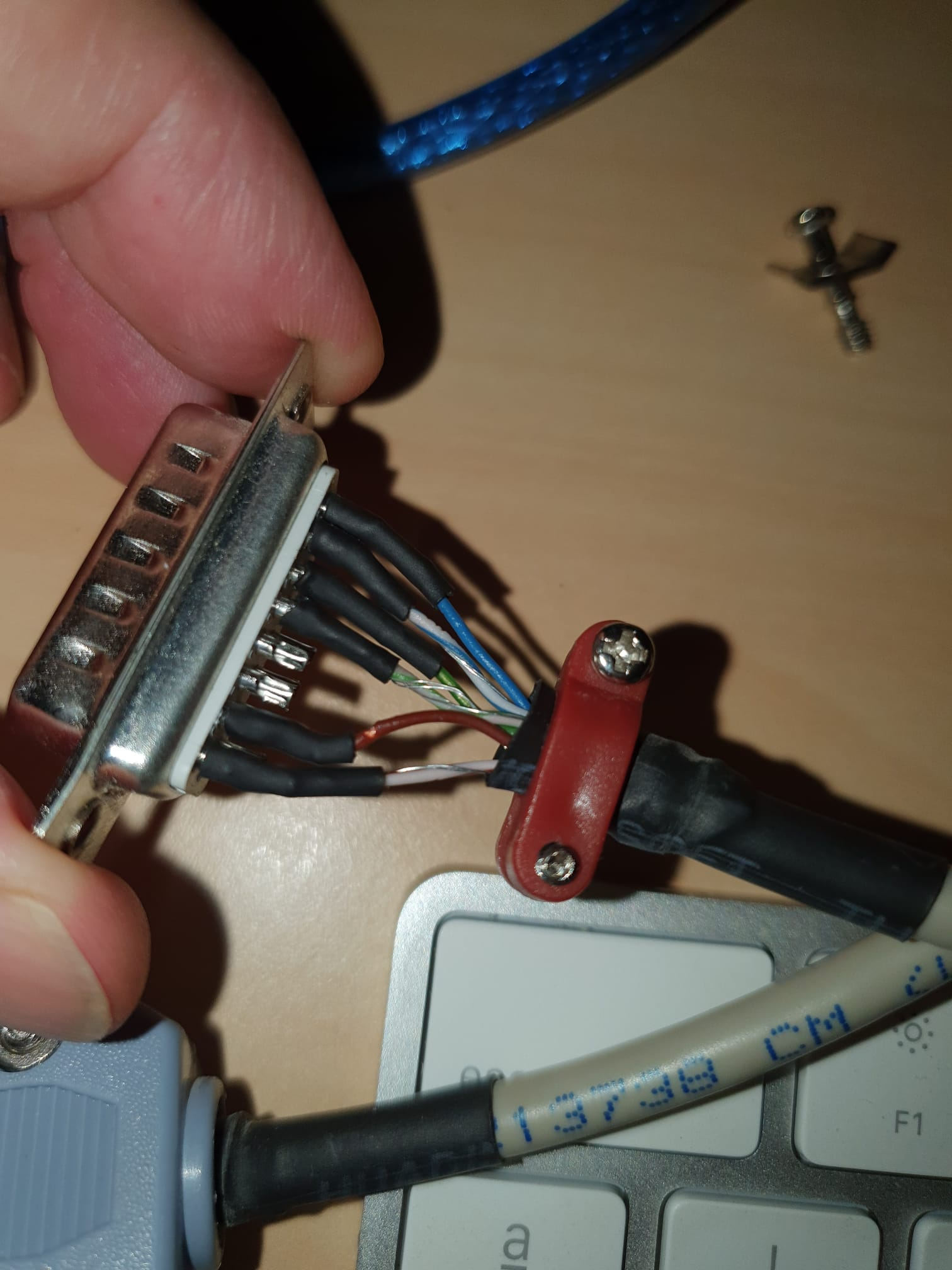
I did not do the wiring.
But it seems the person who did it thought it was a good idea to put a couple of strands of wire to each one of the minus (-) inputs of the driver.
I guess they expected that to be GND, but they did not do the same in all the driver's wires.
So I am guessing the regular symmetric drive of the breakout board can work after we stop shooting in the foot.
-
@dc42 I am glad to report the Duet breakout board works nicely with this driver. All the trouble was due to incorrect wiring.