What should be my first calibration steps on a new build?
-
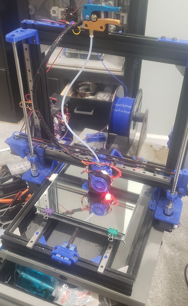
I have a BLV Mod frame and I've built it up with genuine parts.
I'm wanting to print for accuracy as I want to build hobby parts that need to fit together and work. SO, I'm putting it to you, what are my first calibration steps?
What I've done thus far. My bed is level. Hurrah. I can print using mesh bed compensation.
I printed a cube for line thickness testing. I am printing with a .4mm nozzle and with flow rate down to 50% I can get .4 line width. However, doing any other kind of complicated print falls apart with not nearly enough material being layed down.
My e-steps are calibrated on my carriage and extruder as well. So when I move or extrude by X I get X as the number. (Or less than a millimeter)
I'm sure there are already lots of threads on this, but I am having a hard time finding them. so thanks in advance!!
GO!! -
Why would you try to extrude at a 50% flow rate ?
Flow rate is adjusted to fine tune the extrusion rate that you adjusted earlier.
Use 100% unless you have a good reason for any variation.
You can not expect a reasonable print at 50% flow rate. -
Just trying to follow youtube videos and trying to learn. That's why I'm posting here. You're right, the prints are garbage doing anything past a cube, but when I print at 100% I get .8 or greater thickness.. so again.. looking for actual steps or good practices
")
-
You can get the same line thickness as the nozzle size, but it's typically better to add some 20-25% (you can choose but this is a good indication). It makes printing easier and can also be more esthetic.
So I use 0,3mm on a 0.2mm nozzle and 0,5mm with 0,4mm nozzle. Put the 0,5mm in Cura as line width and the flow should then be around 90% (you trest for yourself) to achieve this width and that's then good. Don't go too quick when printing the "vase mode) cube (wall).
Then you want to do the non linear extrusion speed test (m593 or something in that range from the top of my head) to get consistent extrusion amount with different extrusion speed. There are excel sheets here in the forum to help you with the math if you like.
Should cover the line width. Other things to calibrate is retraction and bridging. There are nice tests you can print found on thingiverse.
Holes are typically print too small, cura now had some horizontal expension parameter for getting holes print just right. Might be right for you but I typically use a drill if possible.
Cheers
-
Hi,
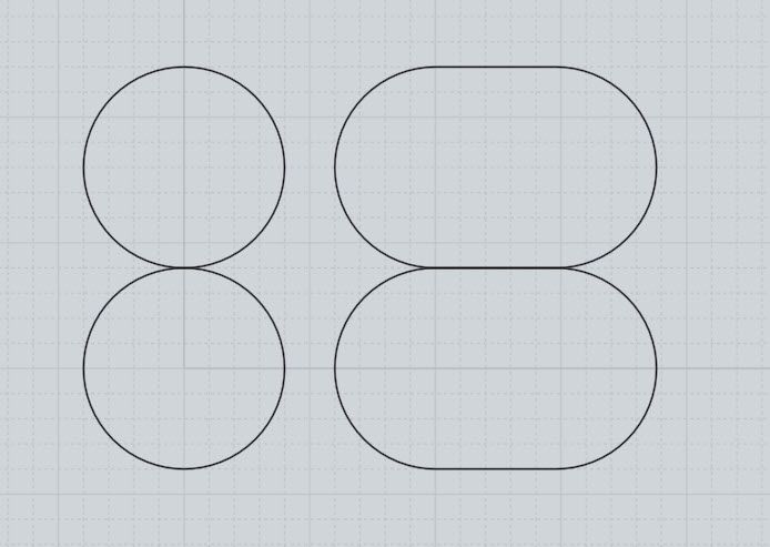
Consider the idealized images below.
The two circles on the left represent using line width that matches the nozzle size.
The two ovals on the right represent using a line width that is greater than the nozzle size.
As you can see you get much more contact between layers with a oval shape.
More contact will normally yield a stronger print.
-
@fcwilt said in What should be my first calibration steps on a new build?:
Hi,
Consider the idealized images below.
The two circles on the left represent using line width that matches the nozzle size.
The two ovals on the right represent using a line width that is greater than the nozzle size.
As you can see you get much more contact between layers with a oval shape.
More contact will normally yield a stronger print.
This is misleading as you play down layer height. If you have a 0.4 mm nozzle and a 0.2 mm layer height you will never get the round shape on the left of your picture.
-
@hbrownell said in What should be my first calibration steps on a new build?:
Just trying to follow youtube videos and trying to learn. That's why I'm posting here. You're right, the prints are garbage doing anything past a cube, but when I print at 100% I get .8 or greater thickness.. so again.. looking for actual steps or good practices
If you print at 100% flow and you get 0.8 mm wide layers but have specified 0.4 mm wide layers in your slicer than you have a mis-configuration someplace. You may have incorrectly set up extrusion steps or you may have a nozzle tat is too low to the build plate.
You said you calibrated the extrusion step value. Did you calibrate that by extruding through the nozzle at the right temperature? Did you mark the filament 100 mm in front of the extruder and then did you do an extrusion of 100 mm? Did the mark on the filament end up just in front of the extruder?
There are multiple ways to specify extrusion flow - for example there is a separate setting for flow for the first layer - did you verify that setting ?
Have you measured what the layer height is (after the build plate cooled down and after you removed your test layer off the bed)? Don't peel the layer with a hot build plate as it will distort the layer you are trying to measure. -
Post your config.g just in case there is something odd there.
What slicer are you using ?
Did you configure your slicer for RRF (Rep Rap Firmware) ? If you have configured the slicer for the wrong firmware, all kinds of odd things start happening.
BTW, you shouldn't have seen a reasonable cube test print either. -
My nozzle is a .4, so again learning I'm thinking I could have a .4 wall. Maybe that's unrealistic. I have a duet3d board and use the configurator to put it together. I'm using cura 4.4.1
I can post my config if that helps.
-
@jens55 said in What should be my first calibration steps on a new build?:
@fcwilt said in What should be my first calibration steps on a new build?:
Hi,
Consider the idealized images below.
The two circles on the left represent using line width that matches the nozzle size.
The two ovals on the right represent using a line width that is greater than the nozzle size.
As you can see you get much more contact between layers with a oval shape.
More contact will normally yield a stronger print.
This is misleading as you play down layer height. If you have a 0.4 mm nozzle and a 0.2 mm layer height you will never get the round shape on the left of your picture.
That's why I qualified it and did not specify a layer height of 0.2.
It was simply to point out the importance of good contact between layers, which under extrusion may prevent.
Frederick
-
You can have a 0.4 mm wall although there is an argument to be made to set your wall line to 0.5 mm (I use 0.4mm line width if I use a 0.4 mm nozzle).
Yes, post your config.g
Have you measured the layer height of your first layer (the one you say is 0.8 mm wide?) -
https://duet3d.dozuki.com/Guide/Ender+3+Pro+and+Duet+Maestro+Guide+Part+4:+Calibration/40
You might get something out of this as a starter.
And then maybe this: https://forum.duet3d.com/post/130939
-
Height is .3
Config
; Configuration file for Duet WiFi (firmware version 1.21)
; executed by the firmware on start-up
;
; generated by RepRapFirmware Configuration Tool v2 on Fri May 24 2019 20:44:40 GMT-0500 (Central Daylight Time); General preferences
G90 ; Send absolute coordinates...
M83 ; ...but relative extruder moves; Network
M550 P"3DPrinter" ; Set machine name
M552 S1 ; Enable network
M586 P0 S1 ; Enable HTTP
M586 P1 S0 ; Disable FTP
M586 P2 S0 ; Disable Telnet; Drives
M569 P0 S0 ; Physical drive 0 goes Backwards
M569 P1 S0 ; Physical drive 1 goes Backwards
M569 P2 S1 ; Physical drive 2 goes forwards
M569 P3 S0 ; Physical drive 3 goes forwards;current settings
M584 X0 Y1 Z2:4 E3; two Z motors connected to driver outputs Z and E1
M671 X-81.5:291.5 Y110:110 S2 ; leadscrews at left (connected to Z) and right (connected to E1) of X axisM350 X16 Y16 Z16 E16 I1 ; Configure microstepping with interpolation
M92 X99.9 Y100.1 Z399.6183 E99. ; Set steps per mm
M566 X900.00 Y900.00 Z12.00 E110.00 ; Set maximum instantaneous speed changes (mm/min)
M203 X6000.00 Y6000.00 Z4000.00 E1200.00 ; Set maximum speeds (mm/min)
M201 X500.00 Y500.00 Z20.00 E250.00 ; Set accelerations (mm/s^2)
M906 X1100.00 Y1100.00 Z1100.00 E1100.00 I30 ; Set motor currents (mA) and motor idle factor in per cent
M84 S30 ; Set idle timeout; Axis Limits old
;M208 X20 Y0 Z0 S1 ; Set axis minima
;M208 X230 Y210 Z200 S0 ; Set axis maxima;New Settings
M208 X-20:230 Y-20:230 ; X carriage moves from 0 to 210, Y bed goes from 0 to 210; Endstops
M574 X1 Y1 S1 ; Set active high endstops; Z-Probe
M574 Z1 S2 ; Set endstops controlled by probe
M307 H3 A-1 C-1 D-1 ; Disable heater on PWM channel for BLTouch
; new suggested settings
M558 P9 H5 F120 T6000 A5 T0.0 ; Set Z probe type to bltouch and the dive height + speeds (F100 T2000 original settings)
;M558 P9 H10 F500 T4000 X0 Y0 Z1 ; Set Z probe type to bltouch and the dive height + speeds (F100 T2000 original settings)
G31 P25 X34.82 Y-8 Z-.033 ; Set Z probe trigger value, offset and trigger height
M557 X0:210 Y15:210 S52.5 ; Define mesh grid; Heaters
M305 P0 T100000 B4138 R4700 ; Set thermistor + ADC parameters for heater 0
M143 H0 S120 ; Set temperature limit for heater 0 to 120C
M305 P1 T100000 B4725 C7.060000e-8 R4700 ; Set thermistor + ADC parameters for heater 1
M143 H1 S280 ; Set temperature limit for heater 1 to 280C; Fans
M106 P0 S0 I0 F500 H T45 ; Set fan 0 value, PWM signal inversion and frequency. Thermostatic control is turned on
M106 P1 S1 I0 F500 H1 T45 ; Set fan 1 value, PWM signal inversion and frequency. Thermostatic control is turned on; Tools
M563 P0 D0 H1 ; Define tool 0
G10 P0 X0 Y0 Z0 ; Set tool 0 axis offsets
G10 P0 R0 S0 ; Set initial tool 0 active and standby temperatures to 0C; Automatic saving after power loss is not enabled
; Custom settings are not configured
; Miscellaneous
M501 ; Load saved parameters from non-volatile memorybed
;Suggested settings from the Duete3D Dozuki.com
G28 ; home
;M401 ; deploy Z probe (omit if using bltouch)
G30 P0 X35 Y105 Z-99999 ; probe near a leadscrew, half way along Y axis
G30 P1 X205 Y105 Z-99999 S2 ; probe near a leadscrew and calibrate 2 motors
;M402 ; retract probe (omit if using bltouch) -
I can't see anything obviously wrong here that would account for your issues.
Are you saying that your first layer is 0.3mm high and 0.8 mm wide ?
What are your slicer settings for first line width and height ? -
That's correct
Layer H .2
Initial Layer H .3
Line Width .4
Wall line .8
Outer .8
Inner .8
Top / Bottom .4
Infill .4
Initiall layer line width 100%Wall line count 1
Top bottom thickness .8
Top layer 2
Bottom layers 2
Enable ironing checked
Infill Desity 40
Infil line distance 1mm
Temp 205
Plate 70
Ratraction Distance 2
Retraction speed 25mm/s
Print speed 40
Enable accelration control checked
Enable jerk control checked -
I am out of ideas, sorry ....
One thing though .... you say you measured line width at 0.8 mm ... was that measuring a SINGLE line or did you measure wall thickness (which is two lines and should be 0.8 mm)? -
Single line