What should be my first calibration steps on a new build?
-
Post your config.g just in case there is something odd there.
What slicer are you using ?
Did you configure your slicer for RRF (Rep Rap Firmware) ? If you have configured the slicer for the wrong firmware, all kinds of odd things start happening.
BTW, you shouldn't have seen a reasonable cube test print either. -
My nozzle is a .4, so again learning I'm thinking I could have a .4 wall. Maybe that's unrealistic. I have a duet3d board and use the configurator to put it together. I'm using cura 4.4.1
I can post my config if that helps.
-
@jens55 said in What should be my first calibration steps on a new build?:
@fcwilt said in What should be my first calibration steps on a new build?:
Hi,
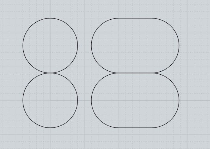
Consider the idealized images below.
The two circles on the left represent using line width that matches the nozzle size.
The two ovals on the right represent using a line width that is greater than the nozzle size.
As you can see you get much more contact between layers with a oval shape.
More contact will normally yield a stronger print.
This is misleading as you play down layer height. If you have a 0.4 mm nozzle and a 0.2 mm layer height you will never get the round shape on the left of your picture.
That's why I qualified it and did not specify a layer height of 0.2.
It was simply to point out the importance of good contact between layers, which under extrusion may prevent.
Frederick
-
You can have a 0.4 mm wall although there is an argument to be made to set your wall line to 0.5 mm (I use 0.4mm line width if I use a 0.4 mm nozzle).
Yes, post your config.g
Have you measured the layer height of your first layer (the one you say is 0.8 mm wide?) -
https://duet3d.dozuki.com/Guide/Ender+3+Pro+and+Duet+Maestro+Guide+Part+4:+Calibration/40
You might get something out of this as a starter.
And then maybe this: https://forum.duet3d.com/post/130939
-
Height is .3
Config
; Configuration file for Duet WiFi (firmware version 1.21)
; executed by the firmware on start-up
;
; generated by RepRapFirmware Configuration Tool v2 on Fri May 24 2019 20:44:40 GMT-0500 (Central Daylight Time); General preferences
G90 ; Send absolute coordinates...
M83 ; ...but relative extruder moves; Network
M550 P"3DPrinter" ; Set machine name
M552 S1 ; Enable network
M586 P0 S1 ; Enable HTTP
M586 P1 S0 ; Disable FTP
M586 P2 S0 ; Disable Telnet; Drives
M569 P0 S0 ; Physical drive 0 goes Backwards
M569 P1 S0 ; Physical drive 1 goes Backwards
M569 P2 S1 ; Physical drive 2 goes forwards
M569 P3 S0 ; Physical drive 3 goes forwards;current settings
M584 X0 Y1 Z2:4 E3; two Z motors connected to driver outputs Z and E1
M671 X-81.5:291.5 Y110:110 S2 ; leadscrews at left (connected to Z) and right (connected to E1) of X axisM350 X16 Y16 Z16 E16 I1 ; Configure microstepping with interpolation
M92 X99.9 Y100.1 Z399.6183 E99. ; Set steps per mm
M566 X900.00 Y900.00 Z12.00 E110.00 ; Set maximum instantaneous speed changes (mm/min)
M203 X6000.00 Y6000.00 Z4000.00 E1200.00 ; Set maximum speeds (mm/min)
M201 X500.00 Y500.00 Z20.00 E250.00 ; Set accelerations (mm/s^2)
M906 X1100.00 Y1100.00 Z1100.00 E1100.00 I30 ; Set motor currents (mA) and motor idle factor in per cent
M84 S30 ; Set idle timeout; Axis Limits old
;M208 X20 Y0 Z0 S1 ; Set axis minima
;M208 X230 Y210 Z200 S0 ; Set axis maxima;New Settings
M208 X-20:230 Y-20:230 ; X carriage moves from 0 to 210, Y bed goes from 0 to 210; Endstops
M574 X1 Y1 S1 ; Set active high endstops; Z-Probe
M574 Z1 S2 ; Set endstops controlled by probe
M307 H3 A-1 C-1 D-1 ; Disable heater on PWM channel for BLTouch
; new suggested settings
M558 P9 H5 F120 T6000 A5 T0.0 ; Set Z probe type to bltouch and the dive height + speeds (F100 T2000 original settings)
;M558 P9 H10 F500 T4000 X0 Y0 Z1 ; Set Z probe type to bltouch and the dive height + speeds (F100 T2000 original settings)
G31 P25 X34.82 Y-8 Z-.033 ; Set Z probe trigger value, offset and trigger height
M557 X0:210 Y15:210 S52.5 ; Define mesh grid; Heaters
M305 P0 T100000 B4138 R4700 ; Set thermistor + ADC parameters for heater 0
M143 H0 S120 ; Set temperature limit for heater 0 to 120C
M305 P1 T100000 B4725 C7.060000e-8 R4700 ; Set thermistor + ADC parameters for heater 1
M143 H1 S280 ; Set temperature limit for heater 1 to 280C; Fans
M106 P0 S0 I0 F500 H T45 ; Set fan 0 value, PWM signal inversion and frequency. Thermostatic control is turned on
M106 P1 S1 I0 F500 H1 T45 ; Set fan 1 value, PWM signal inversion and frequency. Thermostatic control is turned on; Tools
M563 P0 D0 H1 ; Define tool 0
G10 P0 X0 Y0 Z0 ; Set tool 0 axis offsets
G10 P0 R0 S0 ; Set initial tool 0 active and standby temperatures to 0C; Automatic saving after power loss is not enabled
; Custom settings are not configured
; Miscellaneous
M501 ; Load saved parameters from non-volatile memorybed
;Suggested settings from the Duete3D Dozuki.com
G28 ; home
;M401 ; deploy Z probe (omit if using bltouch)
G30 P0 X35 Y105 Z-99999 ; probe near a leadscrew, half way along Y axis
G30 P1 X205 Y105 Z-99999 S2 ; probe near a leadscrew and calibrate 2 motors
;M402 ; retract probe (omit if using bltouch) -
I can't see anything obviously wrong here that would account for your issues.
Are you saying that your first layer is 0.3mm high and 0.8 mm wide ?
What are your slicer settings for first line width and height ? -
That's correct
Layer H .2
Initial Layer H .3
Line Width .4
Wall line .8
Outer .8
Inner .8
Top / Bottom .4
Infill .4
Initiall layer line width 100%Wall line count 1
Top bottom thickness .8
Top layer 2
Bottom layers 2
Enable ironing checked
Infill Desity 40
Infil line distance 1mm
Temp 205
Plate 70
Ratraction Distance 2
Retraction speed 25mm/s
Print speed 40
Enable accelration control checked
Enable jerk control checked -
I am out of ideas, sorry ....
One thing though .... you say you measured line width at 0.8 mm ... was that measuring a SINGLE line or did you measure wall thickness (which is two lines and should be 0.8 mm)? -
Single line