Connecting a 12V PWM FAN when using a 24V power supply
-
Hi guys,
I have a DuetWifi 2 and a Duex2 with a 24V power supply. I would like to connect 12V 4 wire PWM fans to it.
However I'm getting confused on how to wire it correctly. I have a 12V power supply lying around if needed.
I was looking through all the information and noticed:

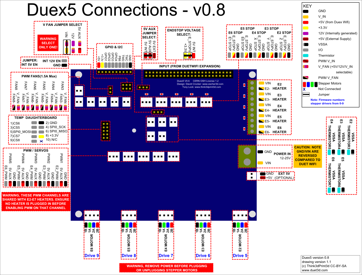
In: https://duet3d.dozuki.com/Wiki/Duex_wiring_diagrams
Does that mean I just set the Jumper and the duex has a buck converter built in? (contrary to what is mentioned in: https://duet3d.dozuki.com/Wiki/Connecting_and_configuring_fans#Section_Using_12V_fans_when_VIN_is_24V)
-
-
@Veti Thank you for taking the time to respond.
According to the documentation the Duex has a internal 12V line though. At least if I interpret it correctly.

Also the expert:
In order to use the 12V internal supply for LEDs/FANs the 12V EN jumper must be fitted. Do not fit this jumper if you are not using the 12V internal supplyIn the above referenced wiki page. Seems to suggest there is a internal 12V power supply.
The FAN's use 1W each so 3W in total which is not a whole lot.
-
you can not use the duex with pwm fans
The F parameter sets the fan PWM frequency, in Hz. The default is F250, which works with most fans, Try F100 or lower if you find that you can't control the speed of your fan. This parameter is ignored for fans connected to the fan outputs of a Duex 2 or Duex 5 because those outputs don't support variable PWM frequency. The F parameter is not supported in RRF_3, use M950 instead.
see https://duet3d.dozuki.com/Wiki/Gcode#Section_M106_Fan_On
-
@Veti According to image they are PWM outputs. The M106 says no variable PWM which would mean changing the frequency (so you're stuck using default, which is not great ofc).
On that note the M950 does not specify any limitation. I am using RRF3 does that mean I can set the PWM frequency indendently.
-
pwm fans require a frequency of 25000HZ. so if you cant change the frequency you wont be able to operate pwm fans.
-
Some 4-pin fans do accept pwm input out of spec, but might be easier to wire them as 2-pin fans and use the default pwm frequency (if that works, its a lottery with most fans)
-
I'd say that's a fair bit of design oversight since 2 pin fans aren't meant to run under PWM and you usually end up with a lot of FAN wine.
Still since there is no limitation described in the M950 RRF3 command does that mean that it will work with that (Changing the frequency I mean)?
I'll probably just move my part cooler fan to the duex so I have three PWM fans and to the 12V thing there.
Might want to add the DUEXes PWM limitations in the specification though. Since "6 additional controlled fan outputs, also usable for driving LEDs etc. The output voltage may be switched between 5V, 12V and VIN." implies that they funtion the same as the controlled fans on the main board.
-
It's true that using PWM on 2 wire fans is a kludge and it's amazing it works at all let alone as well as it does, but 4 wire fans are incredibly uncommon in 3d printer builds up to this point. The Duet 3 adds more 4 wire PWM ports though.
-
It's worth trying your 4-wire fan connected to a DueX fan output in 4-wire mode because AFAIR the Noctua fans are not fussy about the PWM frequency.
If that doesn't work then you could connect the fan red and black wires to the 12V output that recent DueX boards have, and connect the PWM control wire to one of the FAN- outputs on the Duet.
-
@dc42
could you run a wire from the 12V output on the duex to the v_fan pin on the duet to make the duet fans ports 12v as well? -
@Veti said in Connecting a 12V PWM FAN when using a 24V power supply:
@dc42
could you run a wire from the 12V output on the duex to the v_fan pin on the duet to make the duet fans ports 12v as well?Yes that would work too.
-
@dc42 Thnx for the answer. They're indeed noctuas. I say go ugly brown or go home

So just to be sure and not blow anything up:
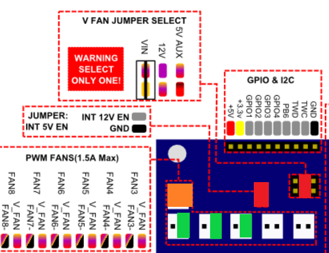
- I have a duex2 0.8

- 2x Red jumper
- 1x Orange for 12V +/- all fans, PWM disabled (couldn't find a 12V out)
- 3x green the PWM lead for the fan
- 3x ? where would the tacho lead go? GPIO 1-3
Please let me know if that would be ok.
Also why does the documentation note only to enable 12V if you use it. Is there a risk in enabling it?
- I have a duex2 0.8
-
Alright so against my better judgement I decided to test somethings out.
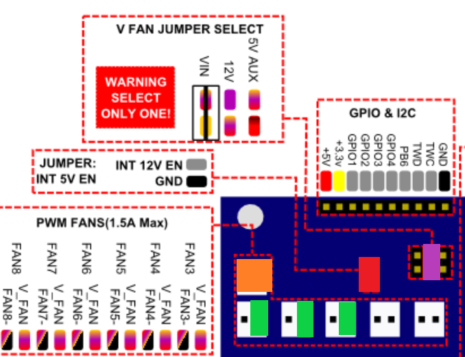
From what I tested the jumper makes the fan output 12V, jay! I have revised my plan of approach:

1x orange is now nothing!
1x red Jumper
1x purple 12V+ for FANs + a wire to short the two pins
3x green PWM signal
1x ground directly to ground of fans
3x tacho still not sure which inputs I can use on duex2 -
Alright, so another update couldn't leave it alone. I can confirm the Noctua runs like a charm. The above image green connections are incorrect! They need to be on FAN-
Now the only open point is the tacho, I don't really think I need it actually. What would be the benefit of connecting it?
-
you can see how fast they are spinning.
-
@Veti which input on the duex can I use for that. The forum names a input on the duet through the extension cable only.
-
you can find PB6 onn the GPIO and I2C header on the duex
-
@Veti does that mean you can only connect one tacho?
-
on the duet2 yes
edit: actually i am not sure if its possible with rrf3 to use additional ones