Help on fixing bed mesh on Delta
-
@Veti ok i'll do some check and maintenance to the axis and retry. I'll post back the results
-
@MikeS also looks like your probe might have some repeatability issues (likely from the same mechanical issues) which is giving you the spikes on your height map. The bed wave seems reasonably consistent though
If you're still struggling, try using the A and S parameters your M558 line of the config. That will make it probe the bed multiple times (up to A parameter times) until it gets two that are within the tolerance (S parameter) and takes the average.
-
So i found a screw that keeps in place the "u joint" on the z-axis to be a little loose. Fixed it. Also increased motor current to be sure to not loosing steps. For the probe i use a IR mini probe and it seems to work fine. I've designed a custom mount for E3D V6 with 2 layer fan and the IR Probe. Here's the model:
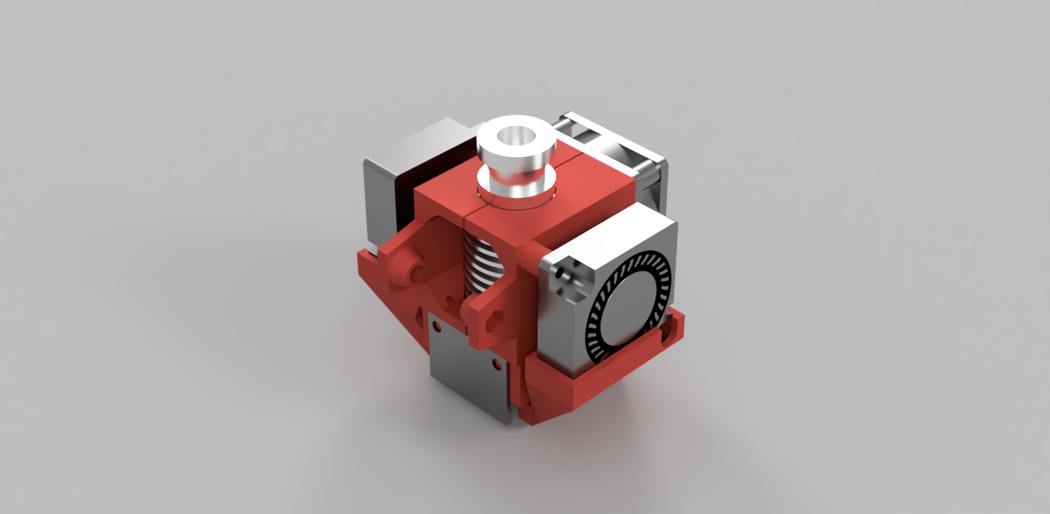
The probe is fixed with 2 screw and seems stable to me also repeatability is ok testing on the same point more time. It's seems that when printer is going right (+X axis) i get higher point than when going left (-X axis). -
So i checked all my axis, tightened all the screws and adjusting all carriages to have less friction possible and loosen a bit the belt because i felt that they were a little tight. After this i get this results:
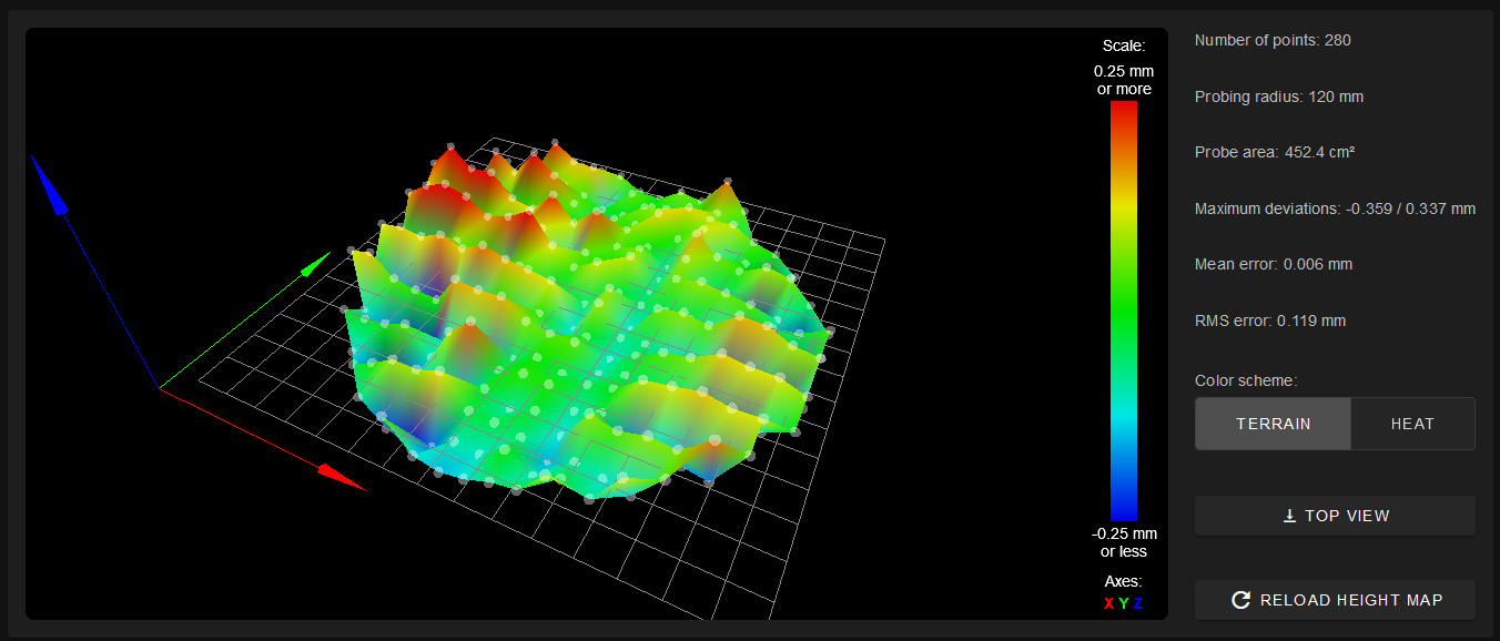
The problem is still there and it crystal clear that i get lower readings on one way of X axis and higher in the other. Because the nature of the delta i don't know wich axis could create this problem. Any suggestion?
-
Hi,
What sort of build surface do you have?
I got a height map with "spikes" something like that from the Mini IR when it sometimes detected the top surface of a transparent build surface, others times the bottom.
Frederick
-
@fcwilt at the moment i'm using a glass plate covere with paper tape to be sure that it's flat as possible. Usually i print on a glass covered with 1mm PEI sheet but it needs tape to work with IR probe and also i think the double tape layer could take to errors in reading. Maybe the "yellow" paper tape is also little transparent to IR?
-
@MikeS said in Help on fixing bed mesh on Delta:
I've designed a custom mount for E3D V6 with 2 layer fan and the IR Probe. Here's the model:
is that a 30mm or a 40mm fan for the hotend cooling?
mind sharing the design? -
can you do an 8 factor again without adjusting the length of the rods? the adjustments from the previous ones where taken over.
with the same number of points as you did in the end? -
@Veti 30mm i think it's the original that came with the V6. Also the blower fan are the ones that came with the printer. Of course i can share, i've designed it in Fusion360 so i only have to understand how to export to usable model also for editing. Tomorrow i'll try at work (installed fusion on work laptop)
-
@Veti i think the 8 factor calculated the same lenght as 7 because i resetted the printer between each test. Also don't have enabled config-override. I've tried a lot of other things right now: swap driver for x/y (tought a bad driver) changed from 16 microsteps interpolated to 32 non interpolated, set higher and lower motor current. The plate is still pretty damn reliable in reading...only problem is the readings are bad!
")
I'll try 8 factor another time of course and post the result. -
@MikeS said in Help on fixing bed mesh on Delta:
@fcwilt at the moment i'm using a glass plate covere with paper tape to be sure that it's flat as possible. Usually i print on a glass covered with 1mm PEI sheet but it needs tape to work with IR probe and also i think the double tape layer could take to errors in reading. Maybe the "yellow" paper tape is also little transparent to IR?
What supports the glass? Could you remove the glass and test without it?
Or perhaps you could spray paint the glass with flat black paint and create the height map using just the painted glass, again just as a test.
Frederick
-
@fcwilt under the glass there is the pcb that act as heated bed. I think that the ir probe will not read if i paint the glass with black on bottom because it's 3mm thick.
-
@MikeS said in Help on fixing bed mesh on Delta:
@fcwilt under the glass there is the pcb that act as heated bed. I think that the ir probe will not read if i paint the glass with black on bottom because it's 3mm thick.
I was thinking of painting the TOP surface.
Frederick
-
@fcwilt ok i could try tomorrow to spray paint it but the fact that the "lines" are aligned with Y axis make me think of a mechanical problem, but can't get what. I don't know delta kinematics so well to see the problem there...
-
18/9/2020, 22:43:53 	M666
Endstop adjustments X-0.69 Y-0.00 Z0.69, tilt X0.63% Y0.77%
18/9/2020, 22:43:50 	M665
Diagonals 269.000:269.000:269.000, delta radius 129.926, homed height 349.851, bed radius 120.0, X -0.165°, Y -0.249°, Z 0.000°
18/9/2020, 22:41:20 	221 points probed, min error -0.291, max error 0.328, mean -0.019, deviation 0.110
Height map saved to file 0:/sys/heightmap.csv
18/9/2020, 22:37:31 	Calibrated 8 factors using 19 points, (mean, deviation) before (0.029, 0.050) after (0.000, 0.032)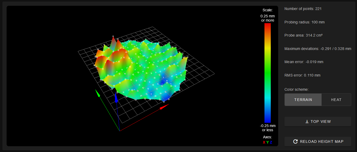
Also tried a lower radius to be sure to not being too much near the printer edges.
Edit: so the machine was bought back in 2014. Is it possible that the timing belt has deteriorate and now the axes are getting bad positions but different based on the position? I haven't made a lot of tall print so used these zone of the belt a lot. At sight they seems ok tho.
-
@MikeS said in Help on fixing bed mesh on Delta:
@fcwilt ok i could try tomorrow to spray paint it but the fact that the "lines" are aligned with Y axis make me think of a mechanical problem, but can't get what. I don't know delta kinematics so well to see the problem there...
Understood but at the very least you will verify that it is NOT a problem with the Mini IR detecting the correct surface.
My first three printers were delta's and I had a difficult time getting them to work as well as I wanted. Then I got my first Cartesian. It worked so much better with so much less effort that I disposed of the delta's and never looked back.
Yet some folks get them working fine. Go figure.
Frederick
-
@fcwilt i think that they don't get them to work "fine" but usable...but i understand them, they are like me: never surrender!

Delta are really pleasant to look at and really neat as aesthetic but i would never recommend one to someone that is not skilled in 3d printing! There is so much to learn and i have lose count years ago on the hours i've spent with this printer. I still hope that with a duet better hardware and firmware i'll manage to get it printing consistently. Tomorrow i'm going to recheck all the joints and mechanics in general...still sure that the problem is there, i hope to get at least the bed at around +-0.1mm at the end. -
just to rule out the ir as a problem you could try this probe
https://de.aliexpress.com/item/32968709878.html
its very check and i use it on my delta because i have no offset using it. -
@Veti I think it won't fit my layer fan mount. I'll get it anyway because it's cheap and could be useful anyway!
However i've a little update. This morning i was checking carriages and arm mount and i felt that there was a little play between u joints and carriages. After disassembly i found that some custom adpater i've made have become a little loose (i think we are talking about some cents of mm). Here are some photos for reference:

Now i've taken all apart, cleaned and tried to fill this little gap with threadlocker. It already feels stiffer but i now must wait 2/3 hours to let it cure. I'll post back with the results of next G32/G29 and see if that fixes something.
-
So after the fix:
M666
Endstop adjustments X0.45 Y0.00 Z-0.45, tilt X0.00% Y-0.39%
M665
Diagonals 269.000:269.000:269.000, delta radius 129.470, homed height 349.814, bed radius 120.0, X -0.431°, Y 0.121°, Z 0.000°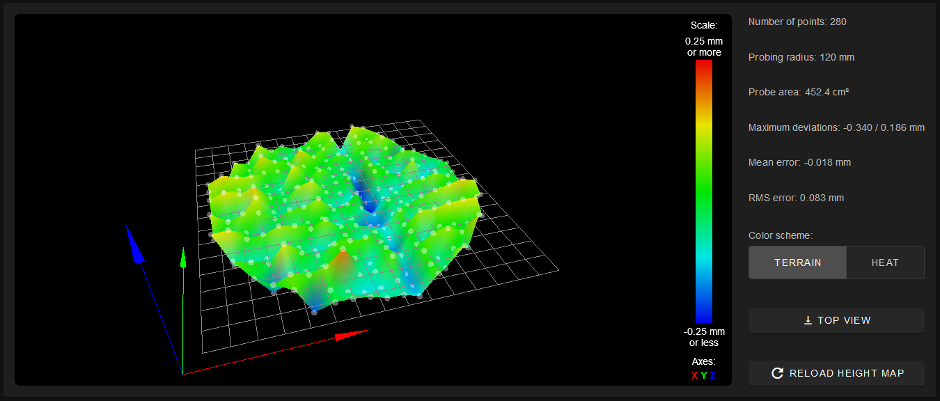
I think to know why there is this blue line along Y axis and will try to fix it. However is it possible to change the probing sequence of G29? I would like to try to probe by column and not by row starting from far left on build plate and going up/down instead of left right, only to see if this lead to more even results among the bed.