IT'S ALIVE!!!
-
Just kidding.
I've been working (again) on my MarkForged style machine.
It has been a test bed for many different concepts I have read about and wanted to try.
It's most recent Z axis motion system had 2 made-to-order 12mm lead screws with 2 mm pitch.
I had them put a 40mm unthreaded section at one end, 8 mm in diameter. This was to accommodate a "genuine" thrust bearing.
The two lead screws were driven by one stepper using a 6mm belt and some pulleys & idlers to connect things together.
It also had 4 made-to-order linear guides for the obvious purpose.
It was a bit of a disappointment.
So based on a system I saw talked about here I decided to try something completely new for me.
I've been meaning to try out auto-leveling with the requisite 3 steppers but that wasn't what was new.
The new concept was using belts for the Z axis.
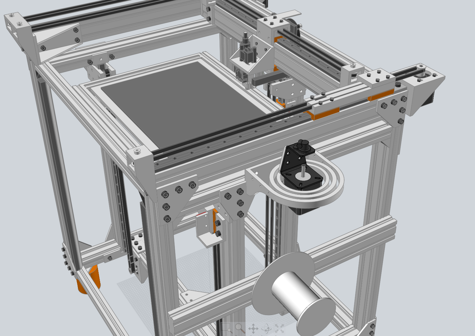
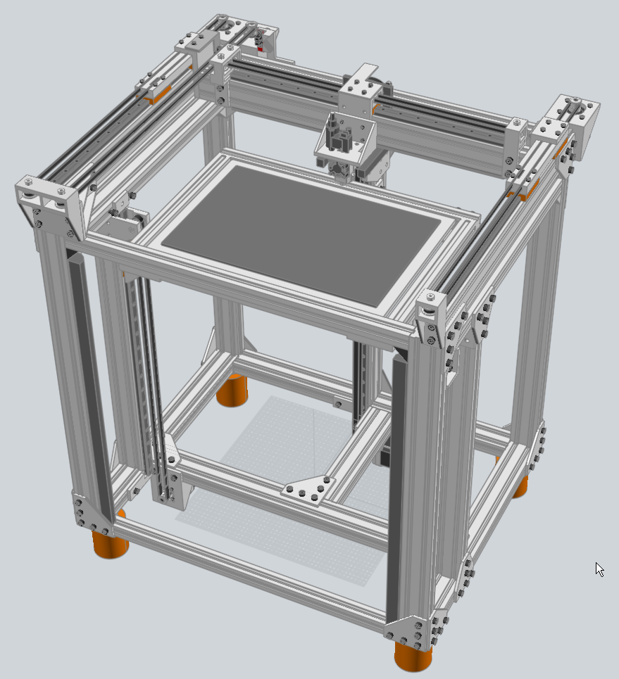
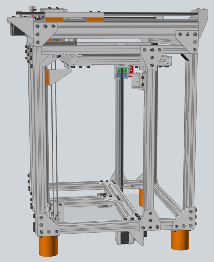
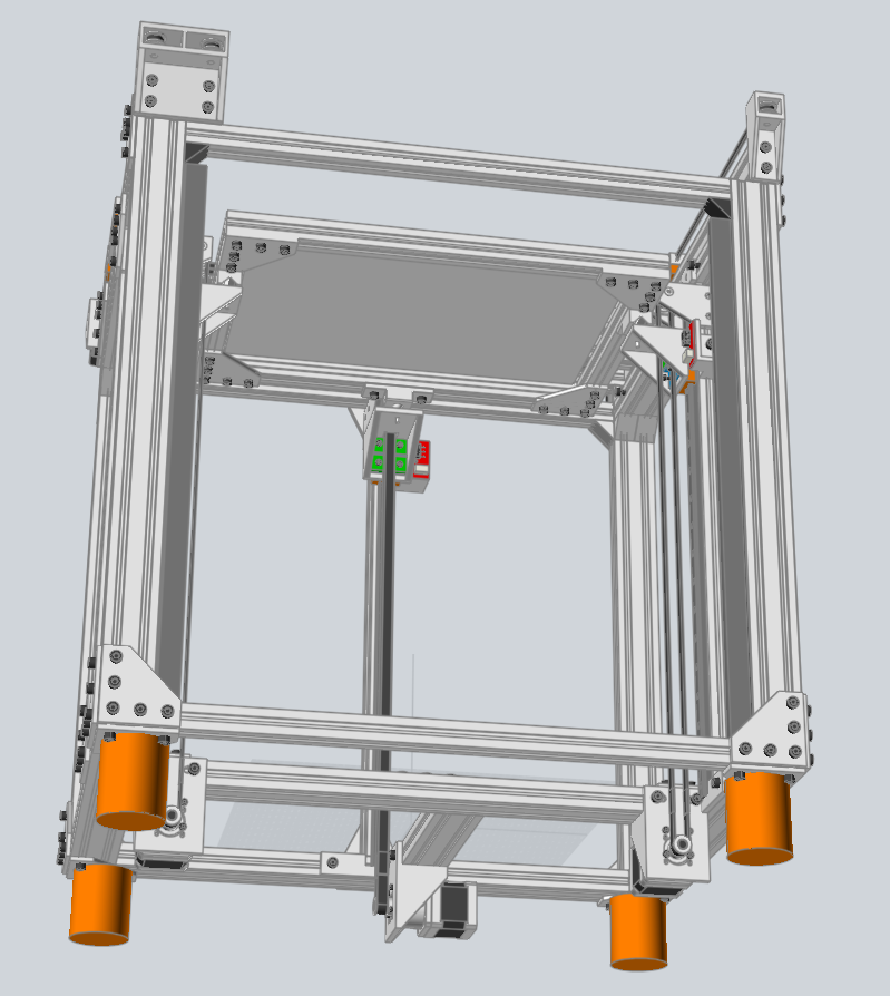
So, long story short, I just fired it up and tested out the 3 steppers with 5-to-1 gearboxes using 2GT 9mm belts which are connected to the linear guide blocks from the previous incarnation (well 3 of the 4 guides).
The parts I needed turned out to be quite simple to design and easy to print.
There is a motor mount with stepper past the lower end of the linear rail, a idler mount with toothed idler past the higher end and a little piece mounted to the linear rail blocks which provides the connection point for the belt and the kinematic joint for supporting the bed.
It's been fun so far.
I just hope it solves the problems I had with the previous setup. It certainly is quiet by comparison.
Frederick
-
have you had a look at the voron 2.4?
it uses belts for z.
i am in the process of converting my ender 3 to a belt driven z machine.
-
Hi,
No I have not seen that printer.
I was simply modifying my existing printer. No plans at this time to start a new one.
Frederick
-
@fcwilt photos?
-
@oliof said in IT'S ALIVE!!!:
@fcwilt photos?
How about a CAD model and/or screen shot of same?
I can take some photos - just need to remember where I put my camera.
Frederick
-
CAD renders are usually super clean without filament spools, cables, etc.; I like to see stuff like cable runs and so on
Not that I'd say no to CAD files or STLs either (-:
-
@oliof said in IT'S ALIVE!!!:
CAD renders are usually super clean without filament spools, cables, etc.; I like to see stuff like cable runs and so on
Not that I'd say no to CAD files or STLs either (-:
You are right, of course, about the CAD files.
It's still a work in progress and the wiring is not yet tidy.
But I'll post what I have a take a few pics despite the unfinished state of the project.
Frederick
-
-
Hi,
I quickly tacked on the gimbal mount for the Nimble stepper and the reel holder.
It's missing the cable connecting the stepper to the Nimble and a reel of filament.
Sorry about that.

Frederick
-
That looks nifty! What's the third stepper on the top for?
-
my guess would be nimble remote drive.
or do you mean the 3 on the belts. 2 for y and one for x it seems. its not a corexy machine.
-
Yeah, it's a markforged as @fcwilt pointed out in the initial post, but the one setup I am aware of can do X and Y with two motors. So I wonder if this is dual Y to take care of the extra weight of the full X axis moving in Y, or something else...
-
@oliof said in IT'S ALIVE!!!:
Yeah, it's a markforged as @fcwilt pointed out in the initial post, but the one setup I am aware of can do X and Y with two motors. So I wonder if this is dual Y to take care of the extra weight of the full X axis moving in Y, or something else...
For starters I'm just a hobbyist and I may have no idea at all what I am doing.

While the graphics you find of this style of printer show one Y stepper, in practice it appears that you have to have something actively moving both ends of the X gantry or it racks something awful.
I suppose I could have found a way to use just one Y stepper but using two steppers seemed like the simplest approach.
You may have noticed that there are two carriages on each Y rail. One article I read mentioned using a long carriage to help control racking of the X gantry. I was trying to use parts I had on hand. So I joined two "normal" carriages together with a big hunk of plastic. I don't know if it had made any difference but it doesn't seem to have hurt.
The weakest link is the connection of the X gantry to the Y carriages. It's a sintered nylon part but it has too much flex. On the todo list is to machine the relevant parts out of aluminum. Someday...
The printer is nice and quiet. It prints well at 90 mm/sec though there is some sort of artifact appearing on vertical surfaces that I have yet to identify as to the cause. You have to hold the part in just the right light to see it.
But I only print functional parts and the faint "blemish" on the surfaces doesn't keep them from being usable.
Tracking down the cause is also on the todo list.
In any case it's fun trying out different ideas, like mounting the stepper driving the Nimble on a gimbal.
And I like the sound of that - "Nimble on a Gimbal".
Frederick
-
I do my design work in a program called "Moment of Inspiration" (MoI for short).
The program works the way I think - or perhaps I think they way it works - regardless I really like it.
While there is a trial download for v3, I am using v4 (beta) which is only available to v3 owners.
I would be happy to share my design files but without v4 I don't know if they would be of any use.
I could export them as a dozens of .step files but that would be not be much good.
Frederick
-
Hey Frederick,
thanks for the insight on the second motor -- offsetting the racking forces that way is pretty smart (at least smarter than whatever I would have come up with).I also believe that a solution that works with the parts at hand is a good solution, common best practice be damned. Innovation doesn't usually come from sticking to what "everybody knows to be best").
I hadn't heard of MoI before (or if I did, I promptly forgot about it). Don't worry about the files, I am in practice not going to build another printer before finishing off the two-and-a-half I am currently working on...
-
@oliof said in IT'S ALIVE!!!:
I hadn't heard of MoI before (or if I did, I promptly forgot about it). Don't worry about the files, I am in practice not going to build another printer before finishing off the two-and-a-half I am currently working on...
Well if you are looking for something different to do download the v3 Moi trial.
It's user interface is different, in a good way I think. And as mentioned it seems to work for me in a very intuitive manor.
Frederick
-
Hi again,
The geared steppers have an odd gearbox ratio of 5 & 2/11 (about 5.18) to 1.
The normal advice about printing using layer heights which allow using whole steps for the Z axis is a bit tricky to apply given that ratio.
A layer height of about 0.193 instead of 0.200 is about as good as you are going to get.
The banding has changed quite a bit BUT it is still there.
Curious.
Frederick


