calibration IR probe RRF3
-
@Phaedrux said in calibration IR probe RRF3:
M98 P "config.g"
I don’t understand, this is my answer with M98 P "config.g" ????
M98 P "config.g"
Warning: Macro file "config.g" not found -
-
thank's

M98 P"config.g"
HTTP is enabled on port 80
FTP is disabled
TELNET is disabled
Error: Invalid use of P parameter
Warning: Heater 0 appears to be over-powered. If left on at full power, its temperature is predicted to reach 460C
Warning: Heater 1 appears to be over-powered. If left on at full power, its temperature is predicted to reach 675C -
@Rudy2A said in calibration IR probe RRF3:
Error: Invalid use of P parameter
you have one invalid command. execute each line separately until you find it.
@Rudy2A said in calibration IR probe RRF3:
M584 X0 Y1 Z2:4 E3 ; set drive mapping
M671 X-58: 317 Y132: 132 S10 ; vis à plomb à gauche (connectées à Z) et à droite (connectées à E1) de l'axe X
M350 X16 Y16 Z16 U16 E16 I1 ; configure microstepping with interpolation
M92 X80 Y80 Z1600 U1600 E830 ; set steps per mm
M566 X600 Y600 Z60 U60 E2400 ; set maximum instantaneous speed changes (mm/min)
M203 X11639 Y11639 Z200 U200 E600 ; set maximum speeds (mm/min)
M201 X800.00 Y800.00 Z40.00 U40.00 E300.00 ; set accelerations (mm/s^2)
M906 X950 Y950 Z950 U950 E1120 I20 ; set motor currents (mA) and motor idle factor in per cent
M84 S30 ; Set idle timeoutYou dont declare a U axis, but configure it afterwards.
-
Honestly, I think I have to reinstall everything!
The more I change settings, the more errors I get.
And the problem is, I'm not sure what to declare in the configuration tool ... I'm not talking about the basics like the dimensions of my machine, the size of my bed, the steps of my motors. But how do I declare a double Z, (Z + U) my heating thermistors… other?
-
-
I redid and redone my files again ... And nothing helps, nothing changes, worse I'm drowning completely.
Someone with good intention to configure me (bass) my printer with the configuration tool. This would be a bass config file with the declared double Z (Z + U). I'm not asking you to do the work for me, I just want to compare files to understand and then be able to reproduce ... It's the only way for me, I know everything is detailed in procedure, but frankly as you can understand, this It's not easy to assimilate everything technically when it is not written in your mother tongue, a period, a comma, a bad translation and find yourself off topic. Thank you for your help.
Sincerely the file comparison method is working for me. it's not to just copy and paste stupidly, it's to be able to continue to understand the RRF3 logic.
-
the reason to go with the configurator is that it generates a config that saves you from small pitfalls.
like order dependency of the commands etc.in your case changing of the M574 for z probe and changing the homing files no to use the endstops.
-
I understand that the configuration tool is there to help me (I do not disagree) and what I ask is that they explain it to me or that they give me a little help to configure it, because it is not easy for me (for lack of fluency in English) to understand everything he asks, it may seem stupid, but I assure you that it is indeed the reality ... with the translation, he gives me a bunch of words that I I have to put things back in order to try to make a solution that is necessarily not always the right one.
The proof, just a simple request for help is already a problem between us, I think the translator does not exactly reproduce my request and makes us go around in circles ... Thank you anyway.
-
ask specific questions where you are unsure in the configurator.
then we can hopefully clarify them.
maybe this helps a bit.
https://duet3d.dozuki.com/Guide/Ender+3+Pro+and+Duet+Maestro+Guide+Part+2:+Configuration/38 -
I assure you that I am not having a bad time. It's like, I wanted to convince you that I made the best wine from home in Corsica by explaining it to you in my written language… I'm sure you'll be more convinced if I gave it to you!
Here are the different stages where I am not comfortable. What should I put for all of these pages?
Mini IR Probe
Genuine E3D V6
Genuine E3D 300X300 bed (Semitec 104GT) 220V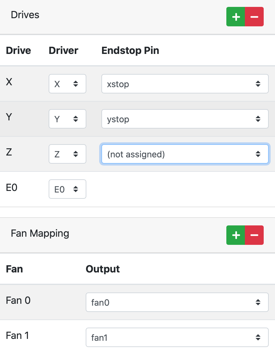

thank's
-
check: Select the first tool on Start-up.
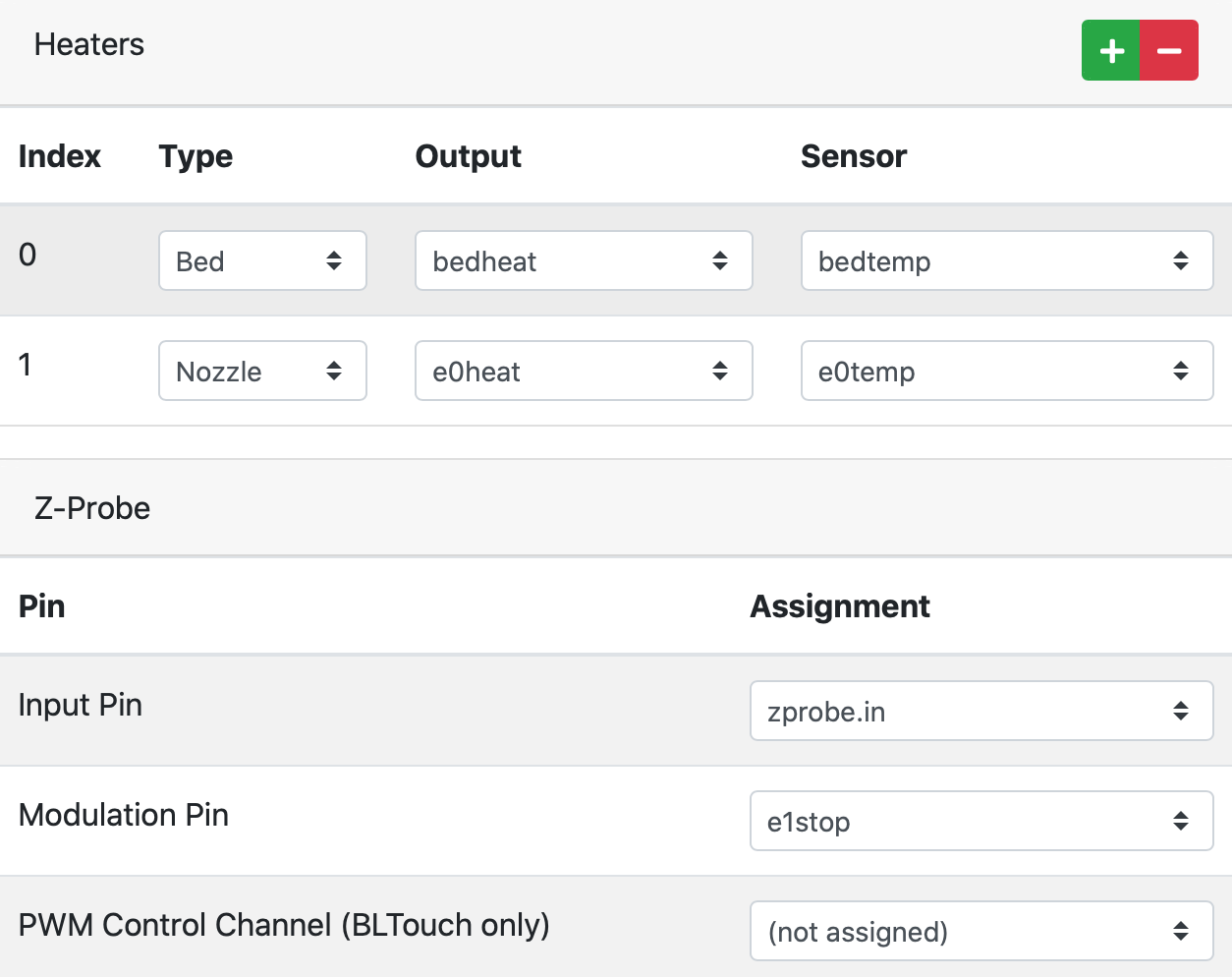
That is helpful for testing.Modulation Pin is not required for the ir probe, as there is no back channel. so set that do not assigned
z enstop to not assigned is ok as well, since you want to use the ir sensor.
for the e3d. in the the heater window. click on the beta field. and select semitec for both bed and hotend.
Add these lines
M307 H0 A435.0 C388.3 D7.8 B0 S0.8 V13.4
M307 H1 A650.7 C221.3 D4.8 B0 S1 V13.3 ; disable bang-bang mode for heater and set PWM limit
to Custom Settings for config.g: on the last page -
Frankly, even installing my original backup file which used to work fine before… I end up with new errors. It's nothing to understand ... I'm sure too stupid. A function that would be nice to add to the configuration tool would be, from the first step. A button checked which would tell us: if you are a big moron, check this box and the answer would be: since you checked this box, take an interest in Marlin (noisier, cheaper, but configurable without any problem). Two years that I was shooting with RRF2 and no problem, easy configuration and good result. Thanks to RRF3, I think my printer will take some distance with me, by propelling it from the 5th floor, I would have created the first flying 3D printer.
-
@Rudy2A come now, don't despair. We will get you there eventually, but only if you don't give up.
Can you post your current config.g please?
Double Z/U axis is not needed in RRF3 if you intend to do leveling with two endstops. You only need a U axis if you want manual control of both Z motors.
In your config above you have these pins define, but those are pin names for the Duet 3. The rest of your pin names for for Duet 2. I think this may be the cause of the invalid use of P parameter.
Can you restate the current problem?
-
First of all, I want to say that I have absolutely nothing against this forum and the people who make it live ... I blame myself and especially not the community for doing its best.
You should also know that I do not speak English and it is very difficult to make yourself understood or to understand you in your answers.
My issue is the following :
I am using a Duet 2 under RRF3.1.1. I absolutely cannot get my Double Z (Z and U) to work independently to level my bed. One of the Z motors is connected to Drive 2 and the other to Drive 4.
When I do a G32, I see the axes (M671) which restore my possible inclination, it works without any problem. On the other hand, for the future with the M557 which runs my two motors, but symmetrically so they do not correct anything since they move equally. I think my whole configuration is corrupted now by dint of modification.
Config.
; Configuration file for Duet WiFi (firmware version 3)
; executed by the firmware on start-up
;
; generated by RepRapFirmware Configuration Tool v3.1.4 on Mon Oct 26 2020 11:25:15 GMT+0100 (CET); General preferences
G90 ; send absolute coordinates...
M83 ; ...but relative extruder moves
M550 P"My Printer+" ; set printer name
M669 K1 ; select CoreXY mode; Network
M552 S1 ; enable network
M586 P0 S1 ; enable HTTP
M586 P1 S0 ; disable FTP
M586 P2 S0 ; disable Telnet; Drives
M569 P0 S0 ; physical drive 0 goes forwards
M569 P1 S0 ; physical drive 1 goes forwards
M569 P2 S0 ; physical drive 2 goes forwards
M569 P3 S0 ; physical drive 3 goes forwards
M569 P4 S0M584 X0 Y1 Z2:4 U4 E3 P3 ; set drive mapping
M671 X-58: 317 Y132: 132 S10; vis à plomb à gauche (connectées à Z) et à droite (connectées à E1) de repère XM350 X16 Y16 Z16 U16 E16 I1 ; configure microstepping with interpolation
M92 X80.00 Y80.00 Z1600.00 U1600.00 E830.00 ; set steps per mm
M566 X600.00 Y600.00 Z60.00 U60.00 E2400.00 ; set maximum instantaneous speed changes (mm/min)
M203 X11639 Y11639 Z200 U200 E600 ; set maximum speeds (mm/min)
M201 X800.00 Y800.00 Z40.00 U40.00 E300.00 ; set accelerations (mm/s^2)
M906 X950 Y950 Z950 U950 E1120 I20 ; set motor currents (mA) and motor idle factor in per cent
M84 S30 ; Set idle timeout; Axis Limits
M208 X0 Y0 Z-0.5 U0-0.5 S1 ; set axis minima
M208 X270 Y270 Z245 U245 S0 ; set axis maxima; Endstops
M574 X1 S1 P"xstop" ; configure active-high endstop for high end on X via pin xstop
M574 Y1 S1 P"ystop" ; configure active-high endstop for high end on Y via pin ystop
M574 Z1 S2 P"io2.in" ; Axe Z avec deux moteurs, butées min.; Z-Probe
M558 P1 C"zprobe.in+zprobe.mod" H5 F120 T6000 ; set Z probe type to unmodulated and the dive height + speeds
G31 P500 X-19 Y6 Z2.58 ; set Z probe trigger value, offset and trigger height
M557 X11:250 Y11:252 S20 ; define mesh grid; Heaters
M308 S0 P"bedtemp" Y"thermistor" T100000 B4725 C7.06e-8 ; configure sensor 0 as thermistor on pin bedtemp
M950 H0 C"bedheat" T0 ; create bed heater output on bedheat and map it to sensor 0
M307 H0 A435.0 C388.3 D7.8 B0 S0.8 V13.4
;M307 H0 B0 S1.00 ; disable bang-bang mode for the bed heater and set PWM limit
M140 H0 ; map heated bed to heater 0
M143 H0 S120 ; set temperature limit for heater 0 to 120C
M308 S1 P"e0temp" Y"thermistor" T100000 B4725 C7.06e-8 ; configure sensor 1 as thermistor on pin e0temp
M950 H1 C"e0heat" T1 ; create nozzle heater output on e0heat and map it to sensor 1
M307 H1 A650.7 C221.3 D4.8 B0 S1 V13.3
;M307 H1 B0 S1.00 ; disable bang-bang mode for heater and set PWM limit; Fans
M950 F0 C"fan0" Q500 ; create fan 0 on pin fan0 and set its frequency
M106 P0 S0 H-1 ; set fan 0 value. Thermostatic control is turned off
M950 F1 C"fan1" Q500 ; create fan 1 on pin fan1 and set its frequency
M106 P1 S1 H1 T45 ; set fan 1 value. Thermostatic control is turned on; Tools
M563 P0 D0 H1 F0 ; define tool 0
G10 P0 X0 Y0 Z0 ; set tool 0 axis offsets
G10 P0 R0 S0 ; set initial tool 0 active and standby temperatures to 0C
; Custom settings are not definedBed.g
; bed.gG28 ; Home all Axes
M561 ; Efface la correction de plan
M290 R0 S0 ; Efface Baby-stepping; Bed levelling (G32)
G30 P0 X0.0 Y132 Z-99999; sonde près d'une vis sans fin, à mi-chemin le long de l'axe Y
G30 P1 X260 Y132 Z-99999 S2; sonde près d'une vis et calibrez 2 moteurs; Espace de sondage
M557 X11:250 Y11:252 P2 ; Définir la grille maillée; Compensation de maillage (G29)
G29 S0homeall.g
G91 ; relative positioning
G1 H2 Z2 F6000 ;
G1 H1 X-275 Y-275 F1000 ; se déplacer rapidement vers la butée X ou Y et s'arrêter là (premier passage)
G1 H1 X-275 ; home X axis
G1 H1 Y-275 ; home Y axis
G1 X4 Y4 F600 ; retour légerement en AR (calage)mm
G1 H1 X-10 ; déplacement lent vers le fin de course de l'axe X
G1 H1 Y-10 ; déplacement lent vers le fin de course de l'axe Y
G90 ; absolute positioning
G1 X129 Y132 F6000 ; Sonde le Z0
G30homez.g
G91 ; Relative mode
G1 Z250 U250 F2000 S1 ; Move up to 250mm in the +Z direction. S1 to stop if endstop is triggered
G1 Z-2 U-2 F600 S2 ; Move 2mm in the -Z direction - (I'm not sure what S2 is for?)
G1 Z3 U3 F100 S1 ; Move slowly 3mm in the +Z direction, stopping at the homing switch
M584 Z2:4 ; Join U to Z again (pay attention to drive numbers used)
G1 Z-5 F3000 ; Move back again 5mm in the -Z direction
G90 ; Back to absolute mode -
@Rudy2A said in calibration IR probe RRF3:
M574 Z1 S2 P"io2.in"
You do not need this. io2.in does not exist on your duet 2. and you don't need to define a z axis endstop if you're using the probe.
@Rudy2A said in calibration IR probe RRF3:
Double Z (Z and U)
You do not need a U axis at all to do leveling using G32/bed.g as you have now.
@Rudy2A said in calibration IR probe RRF3:
homez.g
G91 ; Relative mode
G1 Z250 U250 F2000 S1 ; Move up to 250mm in the +Z direction. S1 to stop if endstop is triggered
G1 Z-2 U-2 F600 S2 ; Move 2mm in the -Z direction - (I'm not sure what S2 is for?)
G1 Z3 U3 F100 S1 ; Move slowly 3mm in the +Z direction, stopping at the homing switch
M584 Z2:4 ; Join U to Z again (pay attention to drive numbers used)
G1 Z-5 F3000 ; Move back again 5mm in the -Z direction
G90 ; Back to absolute modeThis is unnecessary if you are using bed.g to do the leveling.
@Rudy2A said in calibration IR probe RRF3:
M584 X0 Y1 Z2:4 U4 E3 P3 ; set drive mapping
Remove the U4 and all references to the U axis in M92, M350, M566, M203, M201, M906, M208. Remove the P3 as well. You don't need it.
M671 X-58: 317 Y132: 132 S10Remove the space after :Once you have done all of that, G28 should home all axis, and then G32 should perform tilt correction.
-
Apparently, it seems to be out of order (to watch out for) ...
I still have a slight problem calibrating my probe (mini IR).
When it raises its value.=>>
"Nozzle in the center of the bed (usual temperature)
Put the nozzle in contact with the tray (or the sheet of paper)
G92 Z0 (Z = 0)
Lift the 5mm nozzle (G92 Z5)
G30 S-1
Read the z value
G31 Z xxx"I get a height of 2.74 and if I indicate this value G31 Z2.72 my first layer is too crushed ... On the other hand if I go down to 2.62 in manual G31 Z2.62, it is good. Is such a Delta normal?
I am in doubt about my order for the probe, does this seem correct to you?
; Z-Probe
M558 P1 C"zprobe.in+zprobe.mod" H5 F120 T6000 ; set Z probe type to unmodulated and the dive height + speeds
G31 P500 X-19 Y6 Z2.62Thank you one more for your help!
-
@Rudy2A said in calibration IR probe RRF3:
I get a height of 2.74 and if I indicate this value G31 Z2.72 my first layer is too crushed ... On the other hand if I go down to 2.62 in manual G31 Z2.62, it is good. Is such a Delta normal?
yes, the first step is just to get a close value.
fine adjustment should always be made afterwards. -
Thank's @Veti
A small clarification on my values.
If I adjust my leveling on 2 points, my first coat is impeccable. (probe at the four corners of the bed) M557 X11: 250 Y11: 252 P2
If I adjust my leveling on 3 points, my first layer is much too high (probe at the four corners and in the center) M557 X11: 250 Y11: 252 P3
Please note that this is the same part that I am printing and no changes have been made.
-
It depends if you bed is perfectly flat.
If true, g32 is enought
if false, g32 + g29 is needed.