Duet 3 mini Menu Files
-
Playing with the display is on my list to do. I'll let you know what I find.
How did you connect the display to the board? Same pinout as with the Maestro?
-
Thats the odd bit. On the Maestro you need turn the plugs around on the display.
I found i had to put them back the correct way before the screen lights up. -
I'll have to double check. I use a Paneldue so I hadn't been using the stock display, but as part of the mini5 guide I'll get it up and running.
-
install this example menu in the menu directory on the sd card
https://github.com/mudcruzr/Duet-Maestro-12864-Menu-Files/releases
-
@lodger, please check that you are running DWC 3.2 and RRF 3.2. Also that you have enabled the display using an appropriate M918 command in config.g.
-
Mornings,
Right i have double checked i am running up to date RFF and DWC i have even update the wifi server . I have all the menu files correct in the Menu Directory.
I also have:
M918 P1 E4 F2000000 ; configure direct-connect displayIn my config.g
So i am a little lost now.
I dont know if it help but my Diagnostic File say " LCD is idle in state(s) 0"
-
@lodger said in Duet 3 mini Menu Files:
But DWC dose not have a menu section
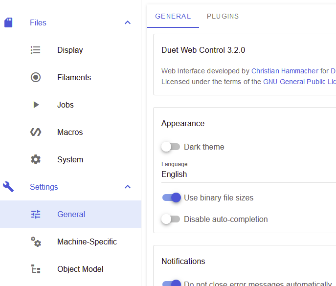
It's called "Display and should be just above "Filaments".

-
Having re done a firmware update this morning I now have display section showing all my files correct..
Running a M918 in the terminal reposts correctly.
So now i am thinking it is a wiring issue. I will look more into it later . The boss is telling me i have to do house work first... : ( -
Ok Have been playing a bit . And i have the FYSETC Mini working fine . but not the ender 3 display.
I am guessing the Enders display is not ST7567 controller. -
@lodger said in Duet 3 mini Menu Files:
Ok Have been playing a bit . And i have the FYSETC Mini working fine . but not the ender 3 display.
I am guessing the Enders display is not ST7567 controller.Correct, the Ender 3 uses a ST7920-based controller, which is P1 in he M918 command, not P2.
Almost all the ST7920-based controllers I have seen are designed to work with 5V signal levels, although I have heard of similar displays working with 3.3v signal levels at reduced speed on other controller boards.
A final complication is that the pinout is different from the Mini 12864, so you would need to make up a special cable, or else modify the display.
-
Thanks Dave.
I am liking the mini Lcd so will print some thing up and use that.
I will sit down next week when i am at work and bored to figure out a lead to get the Enders Display working. If it will work being 5v. If not i will try and find a replacement.I think a lot of folks will want this board on creality marchines.
-
@Veti Had you gotten the Ender 3 display to work with the Mini5+?
-
i have not tried it.
-
just tried connect the ender 3 one and a standard 12864.
all i get is a high pitched noise from the buzzer. cant test more or my neightbours will be annoyed.
no display output.
-
same here.

-
I did connect it up correct using jumper wires to get the correct pin outs .
But still have no success. I did not get much time to play more as the printer is at work. and i was busy.I do think it is 5v issue but i will try mess more next week. as sometimes you can see some txt and the screen flashes on and off i bit.
On a side note i have found a larger ST7567 controller based RGB Screen .looks the same layout and size of the Enders. I have ordered it and will report back if that works.
-
@lodger try reducing the SPI speed. To something like F100000 (add that to the M918)
-
Here are some notes I made when I was looking at this:
- EXP2 is the same on the Mini and the ST7920 display but reversed between them.
- EXP1 is also reversed but has the following additional changes
- The 3 Mini has LCD_A0 where the RRD display expects CS. This is handled in firmware - the firmware uses A0 as CS when a type 1 display is configured in M918.
- The Mini has LCD_RST (which the Mini just ties high through a pullup resistor) where the type 1 display expects SCLK
- The Mini has the CS pin where the type 1 display expects MOSI
- ENCA and ENCB are also swapped, but that doesn't matter, you can change the direction in the M918 command
So I think the easiest way to drive the display would be:
- Reverse the connectors at one end of each cable
- Cut the conductors in the EXP1 ribbon cable that carry LCD_RST and SPI2_CS2 from the Mini to wrong pins on the display
- On the display add links to carry MOSI and SCK from the EXP2 connector to the correct pins on the EXP1 connector
I have not tested this.