Aligning nozzles using baby stepping and global variables
-
I was hoping to use G10 to conduct mid-print nudging of nozzle position, similar to babystepping the Z axis, in order to conduct nozzle alignment on a Tool changing printer. Is this a lost cause? Are G10 offsets only taken into account during an actual tool change?
Goal: Aligning nozzles is a royal pain in rear end and I was hoping to use some parameterised macros and global variables to nudge the head around to get eyeball-perfected nozzle alignment.
Does anyone have any great techniques for aligning nozzles on tool changers?
-
Well you could actually use baby steps on X and Y as well.
https://duet3d.dozuki.com/Wiki/Gcode#Section_M290_Baby_stepping
And there's always TAMV
https://jubilee3d.com/index.php?title=TAMV -
@phaedrux Both great pointers. Thanks.
I wonder if baby stepping X and Y would also impact G53 moves? I don't think Z baby stepping is stored as tool-specific, so neither would X and Y, but in any case, it's a useful pointer that I could use.
I'm still curious if G10 settings are only applied when the given tool is enabled, or if they're fixed once set once, given that the don't seem to have an impact while the tool is being used.
I'll have a play tomorrow with X and Y baby stepping to see if I can get good results with them.
TAMV sounds great, but it's also a bigger climb as I don't have a Pi or PiCam on that machine at the moment.
-
I was able to achieve the results I wanted after @Phaedrux pointed me in the direction of M290.
So here's how I use baby stepping now to achieve alignment-by-eyeball.
Firstly I have some new global variables set up in config.g:
global T2XBase = 20.05 global T2YBase = 45.04 global T2ZBase = -5.625 global T2XNudge = 0.675 global T2YNudge = 0.35 global T2ZNudge = 0.5 global T3XBase = 20.05 global T3YBase = 45.04 global T3ZBase = -5.625 global T3XNudge = 0 global T3YNudge = 0 global T3ZNudge = 0 My nozzle offsets are then setup next in config.g:
G10 P0 X-9 Y40 Z-4.79 ; T0 - V6 G10 P1 X-8.60 Y39.80 Z-4.845 ; T1 - V6 G10 P2 X{global.T2XBase} Y{global.T2YBase} Z{global.T2ZBase} ; T2 - Hemera G10 P3 X{global.T3XBase} Y{global.T3YBase} Z{global.T3ZBase} ; T3 - Hemera Initially, all Nudge values are set to zero. I'm using T3 as my reference, so they stay at zero and other tools need a nudge to align.
Next part is a macro per Tool to create nudging capability. In the macro folder I have a Nudge folder with subfolder T2 and T3 (the ones I'm currently working on). In both T2 and T3 is a nudge.g macro that looks like this, e.g. for T2/nudge.g:
set global.T2XNudge=global.T2XNudge + param.X set global.T2YNudge=global.T2YNudge + param.Y set global.T2ZNudge=global.T2ZNudge + param.Z M290 R0 X{global.T2XNudge} Y{global.T2YNudge} Z{global.T2ZNudge} echo "Tool 2" M290 I then have a set of macros set up under the T2 and T3 folders to result in X, Y, and Z nudges of + and - 0.1. e,g T2/X/+0.1:
M98 P"0:/macros/Nudging/T2/nudge.g" X0.1 Y0 Z0The amount of nudging required for a given tool becomes part of the tNpost.g file, e.g. t2post.g last line:
M98 P"0:/macros/Nudging/T2/nudge.g" X0 Y0 Z0This simply reinstates global nudging for tool after it's properly mounted and out of the dock. Given these nudges could potentially be large, it's important to reset global nudging back to zero when re-docking. So in tNfree.g we have this:
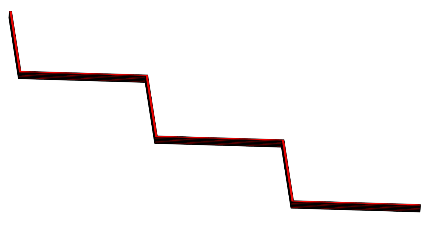
;Reset Babystepping on X and Y M290 R0 X0 Y0 That's the setup complete. Then to use this, I created a print that would help to identify nudging needs. This is a simple zigzag, though I could probably get away with just one line in each direction.
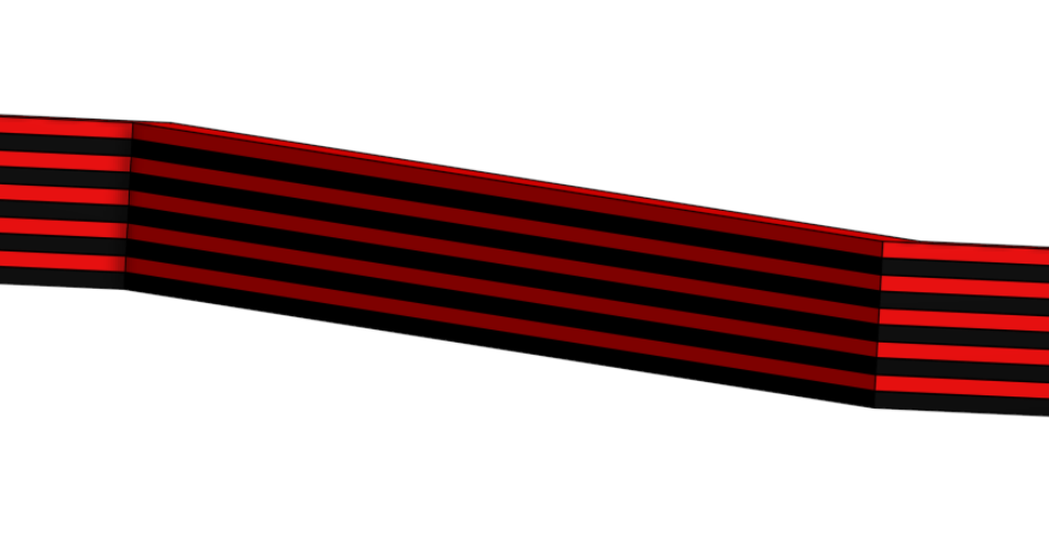
So we're just printing alternate layers with different tools and making the print two nozzle widths thick. After a few layers, or maybe even straight away, once you notice a discrepancy between result and expectation, you can run the nudge macro on T2 to add or subtract 0.1 to X or Y, or simply get the whole macro ready in the console to apply large immediate changes:
M98 P"0:/macros/Nudging/T2/nudge.g" X1.2 Y0.1 Z0Each execution of the macro spits out the current setup for the nudging for this nozzle to the console, and this is also seen in the console for each tool change. Once you have the nozzles aligned, you can copy this output back to config.g and apply the changes to the variables.
I find this works quite well as you can iterate the changes during the print instead of having to complete the print and then makes changes to config.g and restart the whole process again. I was able to get accurate eyeball alignment in just two prints.
Once things looked very close I then used calipers to measure the thickness of the X and Y stacks. If the alignment is good, this should be as per the model design. If not, then an adjustment to X or Y needs to be made of half the difference between the measured result and the design dimension. e.g if you measure the thickness of the line running in the X direction to be 1.1 instead of 1, this is the result of inaccurate alignment in the Y direction. The offset is resulting in overhang on both sides of the column, so a nudge of either 0.05 or -0.05 is needed to the Y nudge value for the nozzle which is out. It should be fairly clear to the naked eye which was it is, depending if the colour of the filament for nozzle in error is hanging out toward the front or back of the column.
Overall this sounds pretty complex now I've written it all down, but in practice, it seems very easy to wield, and a bit more intuitive and rapid than printing entire vernier-gauge prints and then making changes and hoping for the best next time round when you're not 100% certain if your offsets should be + or - to the default nozzle offsets in G10.
Hope this helps someone out there.
-
Gonna move this to the gcode meta command forum because it's a good example of using variables.

