PWM to constant DC voltage for fan control
-
Hiya,
I'd like to connect 12V fans to my Duet 3 Mini 5+ that don’t allow/like PWM control, and feed them a constant voltage (0-12V) based on the PWM duty cycle.
I plan to make a little PCB which sits between the board and fans. Unfortunately I’m not taught in electronics, at all, designing circuits is unknown territory to me. I’ve found this (https://forum.duet3d.com/topic/6227/rc-low-pass-filter-for-blower-fan/9) topic by @wilriker, from which I understand he is trying/tried the same using a Duet 2(?).
His topic includes a schematic, and it seems all I might need is an inductor and capacitor to get this to work? I’m not so sure if the components & values in the schematic are any good for 12V / the Duet 3 Mini 5+ / with my fans

Hope someone can help me out!

PS: my fans have the following specs:
- 4.5~13.8V - 196mA (max)
- 4.5~13.8V - 100mA / max 115mA
-
-
@bananapuppy why not buy some boards from @Egon.net?
https://forum.duet3d.com/topic/21680/designing-a-pwm-to-analog-mini-board-for-fans -
Interesting, I didn't ran into @Egon-Net his post yet. Thanks for sharing it!
From what I gather in the thread, his board seems more complicated/expensive then necessary for my application, maybe; as indicated by this post: https://forum.duet3d.com/topic/21680/designing-a-pwm-to-analog-mini-board-for-fans/50?_=1620147998783
I'll send @Egon-Net a message regardless for sure

-
@bananapuppy said in PWM to constant DC voltage for fan control:
I'd like to connect 12V fans to my Duet 3 Mini 5+ that don’t allow/like PWM control, and feed them a constant voltage (0-12V) based on the PWM duty cycle.
The simplest approach for that application is to connect a 1mH inductor (with a rated current high enough for the fan) between the Duet FAN- output and the fan negative wire, and a capacitor in parallel with the fan, and then increase the Duet PWM frequency to 65535Hz. I suggested an inductor part number that would be suitable for most fans in another thread.
[Edit: I just found that post: https://forum.duet3d.com/post/216923.]
The board made by @Egon-Net is designed to work also with the fan ports on the DueX5, which have fixed PWM frequencies.
-
I've contacted @Egon-Net to score at least one of his boards when he makes the next batch

@dc42 thanks for confirming that again! I'd also like to try that 'simple way' with just the inductor and capacitor for myself. Although I can't find the specific inductor all that conveniently; are the following inductor and capacitor fit for the job? They are 1mH and 1µF, matching the given numbers, but I can't quite judge their other properties.
- RLB0914-102KL BOURNS
- UPS2D010MED NICHICON
Also:
- What if the PWM frequency isn't increased (which might for instance temporarily occur after a reset), does that create any serious issue or potential damage to the Duet?
- Is it normal for capacitors to have a rated lifetime of 2000h? Seems short?

-
@bananapuppy I'm sorry I ran out of time yesterday night...
Here you have some analysis:
This should be the simple LC filter schematic:
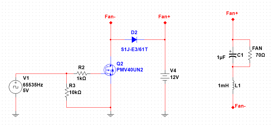
The part on the left is the Duet itself. The part on the right is the fan (modeled as a pure resistor load sinking about 170mA at 12V), with the capacitor in parallel and the inductor in series with Fan-
This is the simulation at 50% PWM, 65KHz:
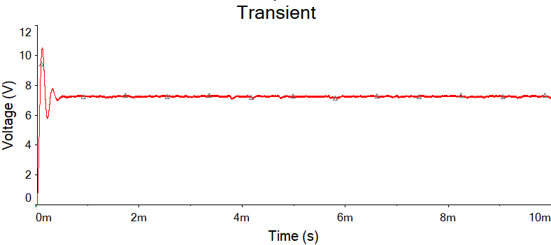
There's some overshoot, but the voltage stabilizes fast, and only a small hint of the PWM frequency remains.
Let's try at 100% PWM, 65KHz:
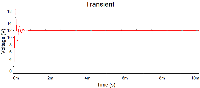
Now the transient gets to 18V, but it also stabilizes fast. I don't think it would be a problem for a fan, but for other kind of loads, it may be.
Now, lets try with a lower frequency, like the one Duex 5 forces on PWM fans (250Hz, IIRC), 50% PWM again:
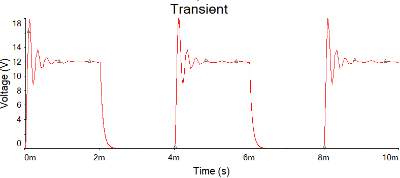
Ouch! Not only the LC filter is too small for that frequency, but it also transients over 18V on each cycle. I wouldn't do that to any of my fans.The resonant transient depends on the L-C values, and in a lesser way on the real impendance of the exact fan you are driving. But for 250Hz L-C should be huge as hell for it to work.
What I do with my board is applying a 3rd order active low-pass RC filter with quite high R's so small capacitors can be used (and no inductors), and a transistor as a current buffer, so there is not transient at all and the frequency can be as low as the Duex 5 is without problems.
-
@bananapuppy said in PWM to constant DC voltage for fan control:
but I can't quite judge their other properties.
- RLB0914-102KL BOURNS
- UPS2D010MED NICHICON
The most important other parameter is maximum current. I'd pick one with at lest double the fan's current.
Also:
- What if the PWM frequency isn't increased (which might for instance temporarily occur after a reset), does that create any serious issue or potential damage to the Duet?
I don't think so. You'll get a transient for every "first" pulse, Duet board would not notice at that level.
- Is it normal for capacitors to have a rated lifetime of 2000h? Seems short?

Electrolytic capacitor's fate. That's life. IIRC, for each 10ºC less than specified, the capacitor doubles its life.
-
@egon-net did you include the resistance of the inductor in your simulation? It's 2.1 ohms for the inductor that @bananapuppy is thinking of using. If the capacitor is electrolytic then you should include its ESR in the simulation too.
What happens if you simulate using a lower value capacitor, or no capacitor at all?
@bananapuppy, that inductor looks OK. It's normal for electrolytic capacitors to have 2000 hour rated life, but that will be at either 85C or 105C. In practice they last much longer at lower temperatures. You can also get 1uF ceramic capacitors.
-
@dc42 said in PWM to constant DC voltage for fan control:
@egon-net did you include the resistance of the inductor in your simulation? It's 2.1 ohms for the inductor that @bananapuppy is thinking of using. If the capacitor is electrolytic then you should include its ESR in the simulation too.
What happens if you simulate using a lower value capacitor, or no capacitor at all?
I added a 2 Ohm series resistor to the inductor, but didn't add anything to the capacitor (I'm used to use low ESR electrolytics). I'll perform a test and show the results.
Regarding the capacitor, the lower the capacitor the smaller the transient, but the worse the ripple too. -
@dc42 here are the results:
2.1 Ohm ESR for Inductor, 7 Ohm ESR for capacitor, 100%PWM:
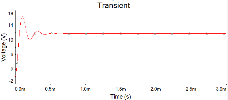
It still overshoots, but less than before.
Now, witha 100nF capacitor, 50% PWM:
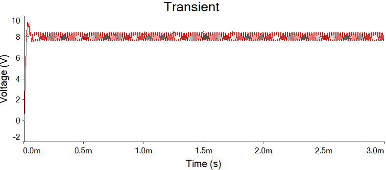
The overshoot is almost gone, but ripple increases.And finally without capacitor at all (same 50% PWM):
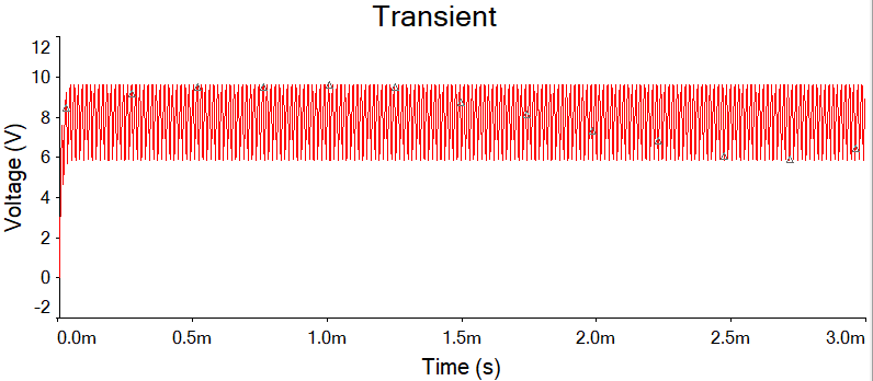
No transient, but lots of ripple. -
@egon-net thanks, looks like 100nF might be a good value to use then.
-
@egon-net thanks for making these graphs, very useful to me! Does the voltage still overshoot to about 16V with 100% PWM, when using a 100nF capacitor?
How about a capacitor somewhere between 100nF and 1µF? I.e. 0.47µF for instance, I figure that might be a nice middle ground for ripple with not too much of an overshoot
 ?
? -
@bananapuppy you are welcome

With a 100nF capacitor the overshoot should be about 1.5V (13.5V max for 12V), and ripple about 1VppThe bigger the cap, the bigger the overshoot.
-
A ripple of 1V p-p is unlikely to matter.
-
@dc42 said in PWM to constant DC voltage for fan control:
A ripple of 1V p-p is unlikely to matter.
I agree.
Is there any drawback for the Duet with the highest PWM frequencies (CPU/resource usage wise) besides a tiny bit more power consumed by the mosfet?
-
-
@bananapuppy said in PWM to constant DC voltage for fan control:
SA105E104MARTB AVX
Ceramic is ok, but I'd try to get one with X5R or X7R dielectric. The one you picked has Z5U dielectric which is not that good.
-
@egon-net no idea what that difference means (if someone can recommend me a good electronics course, please do
 ), but the following should be good then!?
CM-100N-X7R SR PASSIVES
-
@bananapuppy said in PWM to constant DC voltage for fan control:
CM-100N-X7R
Yes, that's 100nF 100V X7R.