Fried my Duet2Wifi?
-
I have an Anycubic Predator with Duet2Wifi. I also have the Delta Smart Effector and Duet PanelDue 7i. It took me about a month to get the wiring and configuration right. After many efforts and several custom parts (fans and whatnot), I finally got everything dialed in just right. It was printing pretty close to perfect, for about two months. I was in heaven.
Then about two weeks ago I noticed these strange printing symptoms where the parts would have a 'melted' appearance over a certain height, say about an inch above the bed. I considered every possible symptom, humidity, a clogged extruder, etc. I had dealt with a lot of issues successfully before but this was a mystery. It didn't seem to fall under any clear symptom except one: mid-print it seems that the extruder was spontaneously increasing the temperature (temp runaway on the hotend?). One possible culprit, one of my two (4010 24V DC) hot end fans was picky. It had started to fail, so I figured that's got to be it...there must have been a change to the cooling mid-print. So I replaced it, booted up the printer again and the fans were running just fine. With no other changes, I initiated a print, then heard a subtle popping sound. Now there is no WIFI response or signal to the PanelDue. I think something shorted the printer. Keep in mind I hadn't touched it, except to replace a simple fan which is easy to do with the plug-and-play nature of the Smart Effector assembly. Of course I did all of this safely with the printer off, etc. And there was no change to the Duet2WIFI wiring.
1.)How to determine if in fact its dead.
2.)Is there a warranty on this? Its been owned for 4 months.
3.)Whether I purchase a replacement or get a warranty replacement, how do I determine the cause so that it never happens again? -
Go through this and see how far you get.
https://duet3d.dozuki.com/Wiki/What_to_do_if_your_Duet_won't_respond
Report back with what you find.
Take the board out entirely and take some pictures, same for the smart effector in case we can spot a failed component.
-
@phaedrux Thanks for your reply. Apologies on the delay to get back (work + taxes).
")
I followed the guide as instructed, with the VIN disconnected, all LED's show up correctly. COM4 port appears and I can even access DWC via wifi (Version 3.2.2). It all seems to work, there are no physical anomalies on the Duet or Smart effector.
Possibly the power supply? Loose power connection (extruder), or a blown fuse?
-
@pschuyler said in Fried my Duet2Wifi?:
Possibly the power supply? Loose power connection (extruder), or a blown fuse?
All possible. Check the fuse for continuity. Check the voltage output of the PSU. Check what LEDs are lit when connected to PSU VIN.
-
@phaedrux Looks like the 7.5Amp (miniblade, brown) fuse has lost continuity. Everything else seems OK so far. Any idea what would cause a short here? Maybe loose wiring somewhere?
Looks like the power connector on the Smart Effector is slightly loose on the PCB. That is, the screws/wires were solidly connected and tight but the connector itself is loose off the PCB, it rocks slightly. Being that my initial problem was with the extruder, I'm betting that this was the problem. Is there a way to obtain a warranty replacement? The Delta Smart Effector is about 4 months old from my purchase. Thanks.
-
@pschuyler said in Fried my Duet2Wifi?:
Maybe loose wiring somewhere?
That's possible. Do you see any signs of burns or damage anywhere on the board?
Replacing the fuse might get you back up and running, but if the source of the short isn't understood first you could be doomed to repeat history and there's no guarantee the fuse will save you a second time.
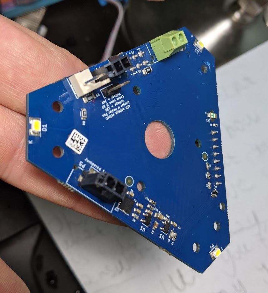
Can you take some photos of the board and smart effector? Does the soldering on the loose connector on the smart effector seem solid or disconnected? -
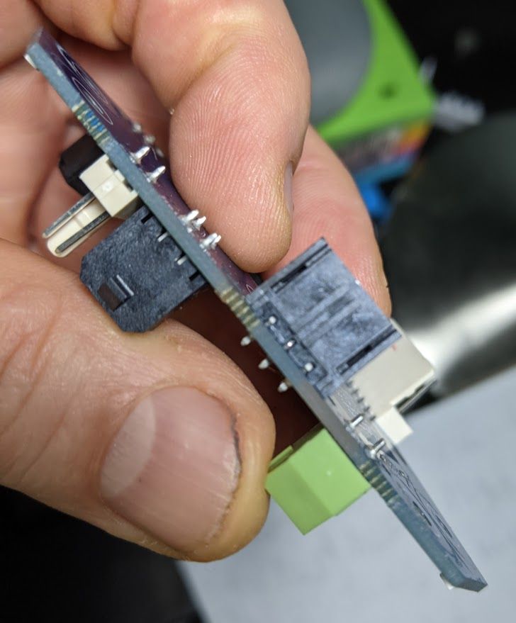
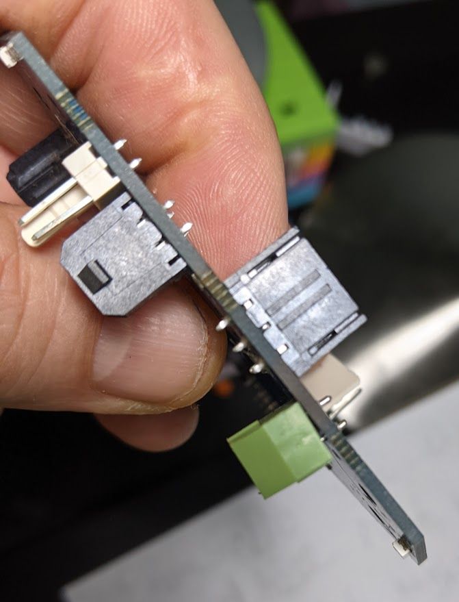
@phaedrux I haven't yet been able to replace the fuse on the Duet, but I have fuses on order. Hopefully the Duet itself is OK. With regard to the Smart Effector and the loose power connector. Notice the green power connector, how it rocks back and forth (compare last two images). The solders on the top side appear to be intact, nothing looks broken or burned...but the green connector is definitely loose.
-
That green connector does look loose, but if the soldered pin is solid the internal screw down terminal could be loose until a wire is screwed down into it. Can you try screwing it down to a wire and see how it looks then?
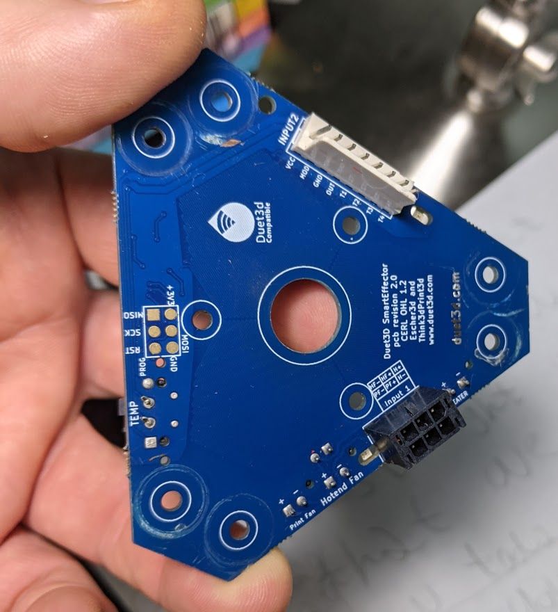
On your second photo it looks like a scratch on a trace from the rod connector, is that the case?
-
@phaedrux The green connector is loose with the screws cranked down as well. Not quite as loose, but still not tight to the PCB. Also there does appear to be a scratch near the Input 2 on the other side. I can't really tell how bad it is....maybe that was from a wrench (while tightening Mag balls?)? Thx.
-
From minds far greater than mine:
The screw terminal being looks looks like the plastic cover, not the pins so unlikely to be the cause of any problems.
It looks like the mag ball ends have damaged the PCB to the point that the copper is showing on the "thermistor 3" trace which should not impact anything except the thermistor readinguse a multimeter to test for a short, from the Duet wiring end, with the wires not plugged into the Duet. then that would be ideal because I am not sure its the smart effector that caused the problem (but of course it could be). Also worth trying another fan (or the old fan that was not working right but at least was not blowing a 7.5A fuse.
7.5A + is a lot of current to take through any of the traces on the board other than the heater so that would be my first point to look. -
@phaedrux It was indeed the fuse, its back working after the 7.5amp fuse was replaced. The Smart Effector was replaced also, just in case. I've also reviewed the wiring and can't see anywhere there might be an issue. Since I've verified the wiring, I'd like to post my config.g just to see if there is something messed up in software:
; Configuration file for Duet WiFi (firmware version 3)
; executed by the firmware on start-up
;
; generated by RepRapFirmware Configuration Tool v3.2.3 on Wed Mar 17 2021 10:36:18 GMT-0500 (Central Daylight Time); General preferences
G90 ; send absolute coordinates...
M83 ; sets extruder moves relative
M550 P"Predator_PS" ; set printer name
M665 R227 L439.46 B185 H443.347 ; Set delta radius, diagonal rod length, printable radius and homed height
M666 X0 Y0 Z0 A0.00 B0.00 ; put your endstop adjustments here, or let auto calibration find them; Network
M552 S1 ; enable network
M586 P0 S1 ; enable HTTP
M586 P1 S0 ; disable FTP
M586 P2 S0 ; disable Telnet; Drives
M569 P0 S1 ; physical drive 0 goes forwards
M569 P1 S1 ; physical drive 1 goes forwards
M569 P2 S1 ; physical drive 2 goes forwards
M569 P3 S1 ; physical drive 3 goes forwards
M584 X0 Y1 Z2 E3 ; set drive mapping
M350 X16 Y16 Z16 E16 I1 ; configure microstepping with interpolation
M92 X160.00 Y160.00 Z160.00 E873.08 ; set steps per mm
M566 X1200.00 Y1200.00 Z1200.00 E1200.00 ; set maximum instantaneous speed changes (mm/min)
M203 X18000.00 Y18000.00 Z18000.00 E1200.00 ; set maximum speeds (mm/min)
M201 X1000.00 Y1000.00 Z1000.00 E1000.00 ; set accelerations (mm/s^2)
M906 X1400 Y1400 Z1400 E1000 I30 ; set motor currents (mA) and motor idle factor in per cent
M84 S30 ; Set idle timeout; Axis Limits
M208 Z0 S1 ; set minimum Z; Endstops
M574 X2 S1 P"xstop" ; configure active-high endstop for high end on X via pin xstop
M574 Y2 S1 P"ystop" ; configure active-high endstop for high end on Y via pin ystop
M574 Z2 S1 P"zstop" ; configure active-high endstop for high end on Z via pin zstop; Z-Probe
M558 P8 R0.4 C"zprobe.in+zprobe.mod" F1200 T6000 ; set Z probe type to unmodulated and the dive height + speeds
;M558 H5
G31 P100 X0 Y0 Z-0.14 ; set Z probe trigger value, offset and trigger height
M557 R175 S30 ; define mesh grid; Hotend
M308 S1 P"e0temp" Y"thermistor" T100000 B3950 ; sensor 1
M950 H1 C"e0heat" T1 ; create heater and map sensor 1
M143 H1 S270 ; Set temperature limit for heater 1 to 270C; Bed Heater
M308 S0 P"bedtemp" Y"thermistor" T100000 B4138 ; configure sensor 0 as thermistor on pin bedtemp
M950 H0 C"bedheat" T0 ; create bed heater output on bedheat and map it to sensor 0
M307 H0 A137.8 C533.3 D1.5 V24.3 B0 ; Disable bang-bang mode for the bed heater and set PWM limit
M305 P1 T100000 B4300 C0 R4700 ; Set thermistor + ADC parameters for heater 0
M140 H0 ; map heated bed to heater 0
M143 H0 S105 ; Set temperature limit for heater 0 to 105C; Fans
M950 F0 C"fan0" Q500 ; create fan 0 on pin fan0 and set its frequency
M106 P0 S0 H-1 ; set fan 0 value. Thermostatic control is turned off
M950 F1 C"fan1" Q500 ; create fan 1 on pin fan1 and set its frequency
M106 P1 S1 H1 T45 ; set fan 1 value. Thermostatic control is turned on; Tools
M563 P0 D0 H1 F0 ; define tool 0
G10 P0 X0 Y0 Z0 ; set tool 0 axis offsets
G10 P0 R0 S0 ; set initial tool 0 active and standby temperatures to 0C; Extruder
M404 N1.75 ; Set for print monitor
M569 P3 S1 ; Drive 3 goes forwards
M592 X160.00 Y160.00 Z160.00 E830 ; Set steps per mm
M572 D0 S0.1 ; Pressure Advance on Extruder
M500 ; store setting; Miscellaneous
M575 P1 S1 B57600 ; enable support for PanelDue
M501 ; Load saved parameters from non-volatile memory; Filament monitoring
M591 P2 C"e1stop" S1 D0 ; Activate filament sensor connected to E1 endstop
M581 T1 S0 R0 E1 ; trigger for filament runout sensor, T4 = trigger number
;M591 D4 P2 C4 ; filament monitor connected to E1_stop; Estop button
M950 J0 C"!^E0stop" ; Input 0 uses e0Stop pin, inverted, pullup enabled
M581 E0 P"E0stop" S0 T1 C1 ; Estop command, (E0) monitor Extruder 0, (P7) pin name, (S1) trigger on active-inactive edge, (T1) pause command, (C1) monitor during printing
M581 E0 P"E0stop" S1 T9 C1 ; (T9) Activate 'trigger9.g', (E2)Monitor Estop 2, (S1)Trigger on raising edge, (C1)Only during print. This is the 2nd estop command, when condition changes it launches "trigger9.g" -
@pschuyler said in Fried my Duet2Wifi?:
M558 P8 R0.4 C"zprobe.in+zprobe.mod" F1200 T6000 ; set Z probe type to unmodulated and the dive height + speeds
;M558 H5With that M558 H5 commented out you don't have a dive height set. Unless you have it set somewhere else I can't see. You can send M558 by itself to see what it reports it as.
@pschuyler said in Fried my Duet2Wifi?:
M500 ; store setting
You likely don't want this in your config.g It's meant to store measured or calculated results like PID tuning and offsets.
@pschuyler said in Fried my Duet2Wifi?:
M592 X160.00 Y160.00 Z160.00 E830 ; Set steps per mm
M592 is for non-linear extrusion. M92 is steps per mm. Not sure what you're trying to set there.
You can check your config.g for other syntax errors by sending M98 P"config.g" in the console.
-
@phaedrux Thanks for the reply. I'll start by removing the M500 command.
After sending M558 in the console, "M558
Z Probe 0: type 8, input pin zprobe.in, output pin zprobe.mod, dive height 5.0mm, probe speed 1200mm/min, travel speed 6000mm/min, recovery time 0.40 sec, heaters normal, max taps 1, max diff 0.03"(;M558 H5) I had read somewhere in the documentation that the M558 H command was supposed to be commented out after initial calibration. Since the dive height appears to be 5.0mm, it should be:
M558 H5
(not commented out, right?)(M592 X160.00 Y160.00 Z160.00 E830 ; Set steps per mm) It was supposed to be M92, not M592, lol that's a messed up keyboard typo. I wonder if that could have been the source of the problem? Perhaps it was assuming it was non-linear extrusion and overloading the motor? I have a Bondtech BMG extruder (which normally requires E415 stepping), but I also have a stepper motor which is .9 degrees, not the more common 1.8 deg. If I'm right it should be:
M92 X160.00 Y160.00 Z160.00 E830
One other question: M203 X18000.00 Y18000.00 Z18000.00 E1200.00 ; set maximum speeds (mm/min)
Are these maximum speeds too high? Can you see anywhere there could be an overloading condition that might break a fuse?Thanks!
-
@pschuyler said in Fried my Duet2Wifi?:
I had read somewhere in the documentation that the M558 H command was supposed to be commented out after initial calibration.
Normally there are two values. The first one in the main line is H5 and the second line that has the note to comment it out is a much larger dive height value like H30 just to give extra clearance. Once you have things calibrated you can comment that one out to use the more normal value of 5mm.
Looks like 5mm is the default anyway. I'd just add the H5 back to the main M558 line.
I don't think it would have accepted that M592 line since it doesn't include the correct syntax. It would likely just give an error.
You already have M92 higher up in the config anyway, so best to eliminate that second one for clarity sake.
Those max speeds don't look too crazy for a delta printer and certainly wouldn't cause a fuse to blow.
If you send M98 P"config.g" in the console you can check for any other syntax errors.
-
@phaedrux The Plot thickens (see image). Performed my first print, but I get the same weird upper-level (overheating?) issues that happened before the troubles. Can't locate anything in the wiring setup. What could cause a printer to do have this weird effect on the upper sections of a print (last ~15%)? Some banding issues too, but I believe I can diagnose that separately. Fans appear to be working fine. Temps are OK. Overheating it seems.
Could it be bad thermistor settings?
Extrusion parameter incorrect? (previous config had two different settings for M92 Esteps).
I'll change filament, that's about the only thing I haven't tried.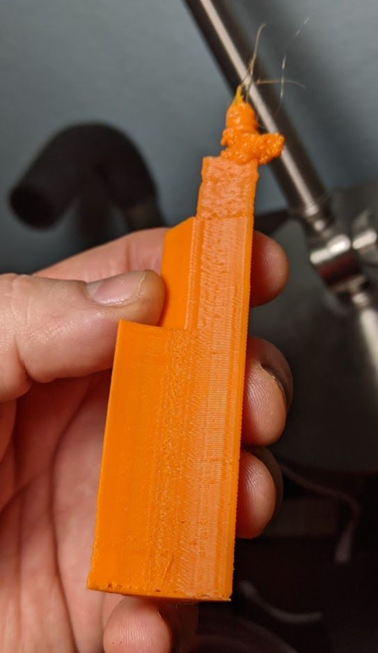
-
If the top of that model is a small area tower then yes overheating is likely. Your slicer will have some sort of minimum layer time and fan speed settings so that on small areas like that it will slow down and increase the fan speed to try and keep the previous layer cool. It can also help to print a separate tower object the same height a little ways away from the main model. It will use more plastic on a useless tower but it will give the layers more time to cool. You could also print two of the main object.