Duet3D Logo Duet3D
    • Tags
    • Documentation
    • Order
    • Register
    • Login

    24V Endstop on Duet3 6MB

    Scheduled Pinned Locked Moved
    Duet Hardware and wiring
    3
    17
    524
    Loading More Posts
    • Oldest to Newest
    • Newest to Oldest
    • Most Votes
    Reply
    • Reply as topic
    Log in to reply
    This topic has been deleted. Only users with topic management privileges can see it.
    • neo0204undefined
      neo0204
      last edited by neo0204

      Hi,

      I have got a new Duet3 6MB and I am very new to this field.

      I have got the iGus gantry which I am able to move around and have set up the senserless homing.

      Now I would like to install the igus 24V inductive sensors NPN NO.

      I got the 24V endstop because the duet documents say that Duet3 6MB can handle end stop up to 30V.

      But they seem to not work, there is no LED when connected the Vcc wire to 3.3V or 5V.

      Please help here.

      PS: I have tried the general microswitch endstops and they are working fine.

      jay_s_ukundefined 1 Reply Last reply Reply Quote 0
      • jay_s_ukundefined
        jay_s_uk @neo0204
        last edited by

        @neo0204 you'll need to take 24v power from your PSU and then feed the signal back to the input pin of the input/output you want to use

        Owns various duet boards and is the main wiki maintainer for the Teamgloomy LPC/STM32 port of RRF. Assume I'm running whatever the latest beta/stable build is

        neo0204undefined 1 Reply Last reply Reply Quote 1
        • neo0204undefined
          neo0204 @jay_s_uk
          last edited by

          @jay_s_uk Thank you for your response.

          Just to confirm, The Vcc and GND wire of the end-stop should be connected to PSU and only the signal will be connected to input/output.

          Also would you please help on which pin (input/output) to use for 24V NPN Normally open end stop.

          Apologies if my queries are too basic.

          jay_s_ukundefined 1 Reply Last reply Reply Quote 0
          • jay_s_ukundefined
            jay_s_uk @neo0204
            last edited by

            @neo0204 said in 24V Endstop on Duet3 6MB:

            The Vcc and GND wire of the end-stop should be connected to PSU and only the signal will be connected to input/output.

            Correct, although you can also use the ground pin on the IO you're using

            @neo0204 said in 24V Endstop on Duet3 6MB:

            Also would you please help on which pin (input/output) to use for 24V NPN Normally open end stop.

            A pin labelled .in
            3bd04f6d-e1f6-4916-ac7c-f032d626d58a-image.png

            Owns various duet boards and is the main wiki maintainer for the Teamgloomy LPC/STM32 port of RRF. Assume I'm running whatever the latest beta/stable build is

            neo0204undefined 1 Reply Last reply Reply Quote 1
            • neo0204undefined
              neo0204 @jay_s_uk
              last edited by

              @jay_s_uk
              Thank you, Now the sensor detects power, and when manually triggered the LED on the sensor goes ON.

              Sensor Vcc and GND are connected to PSU 24V and GND respectively.
              Sensor Signal is connected to pin io0.in

              But When trying M119 command from DWC it says

              Endstops - X: not stopped, Y: not stopped, Z: not stopped,
              

              Here is the config.g file,

              ; Configuration file for Duet 3 (firmware version 3)
              ; executed by the firmware on start-up
              ;
              ; generated by RepRapFirmware Configuration Tool v3.2.3 on Mon May 17 2021 21:56:13 GMT+0530 (IST)
              
              ; General preferences
              G90                                      ; send absolute coordinates...
              M83                                      ; ...but relative extruder moves
              M550 P"My_Controller_2"                  ; set printer name


              ; Drives
              M569 P0.0 S0                             ; physical drive 0.0 goes forwards
              M569 P0.1 S0                             ; physical drive 0.1 goes forwards
              M569 P0.2 S0                             ; physical drive 0.2 goes forwards
              M569 P0.3 S0                            ; physical drive 0.3 goes forwards
              M584 X0.0 Y0.1 Z0.2 E0.3                 ; set drive mapping
              M350 X16 Y16 Z16 E16 I1                  ; configure microstepping with interpolation
              M92 X80.00 Y80.00 Z80.00 E420.00         ; set steps per mm
              M566 X900.00 Y900.00 Z900.00 E120.00     ; set maximum instantaneous speed changes (mm/min)
              M203 X6000.00 Y6000.00 Z6000.00 E1200.00 ; set maximum speeds (mm/min)
              M201 X500.00 Y500.00 Z500.00 E250.00     ; set accelerations (mm/s^2)
              M906 X2000 Y2000 Z800 E800 I30           ; set motor currents (mA) and motor idle factor in per cent
              M84 S30                                  ; Set idle timeout
              
              ; Axis Limits
              M208 X0 Y0 Z0 S1                         ; set axis minima
              M208 X400 Y400 Z150 S0                   ; set axis maxima
              
              
              ; Endstops
              M574 X1 S1 P"!io0.in"                  
              M574 Y1 S1 P"!io1.in"                  
              M574 Z1 S1 P"!io2.in"                  
              
              ; Z-Probe
              M558 P0 H5 F120 T6000                    ; disable Z probe but set dive height, probe speed and travel speed
              M557 X15:215 Y15:195 S20                 ; define mesh grid
              
              ; Heaters
              
              ; Fans
              
              ; Tools
              
              ; Custom settings are not defined


              Also, I tried changing the end-stops pin to,

              ; Endstops
              M574 X1 S1 P"!io0.in"                  
              M574 Y1 S1 P"!io1.in"                  
              M574 Z1 S1 P"!io2.in" 
              

              The M119 command returns below response,

              Endstops - X: is at min, Y: is at min Z: is at min,
              
              jay_s_ukundefined 1 Reply Last reply Reply Quote 0
              • jay_s_ukundefined
                jay_s_uk @neo0204
                last edited by

                @neo0204 are you testing them with M119 in both the triggered and untriggered state?
                it will only report the state they are in at that moment in time
                best to make sure they aren't triggered (LED unlit) and run M119. Then trigger them and do the same

                Owns various duet boards and is the main wiki maintainer for the Teamgloomy LPC/STM32 port of RRF. Assume I'm running whatever the latest beta/stable build is

                neo0204undefined 2 Replies Last reply Reply Quote 0
                • neo0204undefined
                  neo0204 @jay_s_uk
                  last edited by

                  @jay_s_uk Yes, i am testing it in both states.
                  But it's giving the same results on M119.

                  jay_s_ukundefined 1 Reply Last reply Reply Quote 0
                  • neo0204undefined
                    neo0204 @jay_s_uk
                    last edited by

                    @jay_s_uk Also when the sensor is triggered, I checked with the multimeter, and it's passing the 24V signal to the board.

                    Am I am missing something in the config file or at the firmware level?

                    1 Reply Last reply Reply Quote 0
                    • jay_s_ukundefined
                      jay_s_uk @neo0204
                      last edited by

                      @neo0204 I take it the 24v PSU you are using is the same one you are powering the board with?
                      you may need to use the internal pullup resistor.
                      add a ^ to the pin name

                      Owns various duet boards and is the main wiki maintainer for the Teamgloomy LPC/STM32 port of RRF. Assume I'm running whatever the latest beta/stable build is

                      neo0204undefined 1 Reply Last reply Reply Quote 0
                      • neo0204undefined
                        neo0204 @jay_s_uk
                        last edited by

                        @jay_s_uk Yes the PSU is the same,

                        Like this?

                        M574 X1 S1 P"!^io0.in" 
                        
                        jay_s_ukundefined 1 Reply Last reply Reply Quote 0
                        • jay_s_ukundefined
                          jay_s_uk @neo0204
                          last edited by

                          @neo0204 yep

                          Owns various duet boards and is the main wiki maintainer for the Teamgloomy LPC/STM32 port of RRF. Assume I'm running whatever the latest beta/stable build is

                          neo0204undefined 1 Reply Last reply Reply Quote 0
                          • neo0204undefined
                            neo0204 @jay_s_uk
                            last edited by

                            @jay_s_uk I tried this yesterday and sadly it's not working.

                            What else I can do to make it work?

                            1 Reply Last reply Reply Quote 0
                            • dc42undefined
                              dc42 administrators
                              last edited by

                              @neo0204 said in 24V Endstop on Duet3 6MB:

                              @jay_s_uk Also when the sensor is triggered, I checked with the multimeter, and it's passing the 24V signal to the board.

                              Am I am missing something in the config file or at the firmware level?

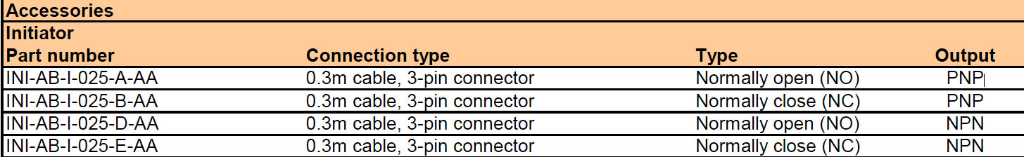
                              An NPN sensor will not output 24V. I suspect you have a PNP sensor.

                              Duet WiFi hardware designer and firmware engineer
                              Please do not ask me for Duet support via PM or email, use the forum
                              http://www.escher3d.com, https://miscsolutions.wordpress.com

                              neo0204undefined 1 Reply Last reply Reply Quote 0
                              • neo0204undefined
                                neo0204 @dc42
                                last edited by

                                @dc42 Thank you for your response.

                                EndStop.png

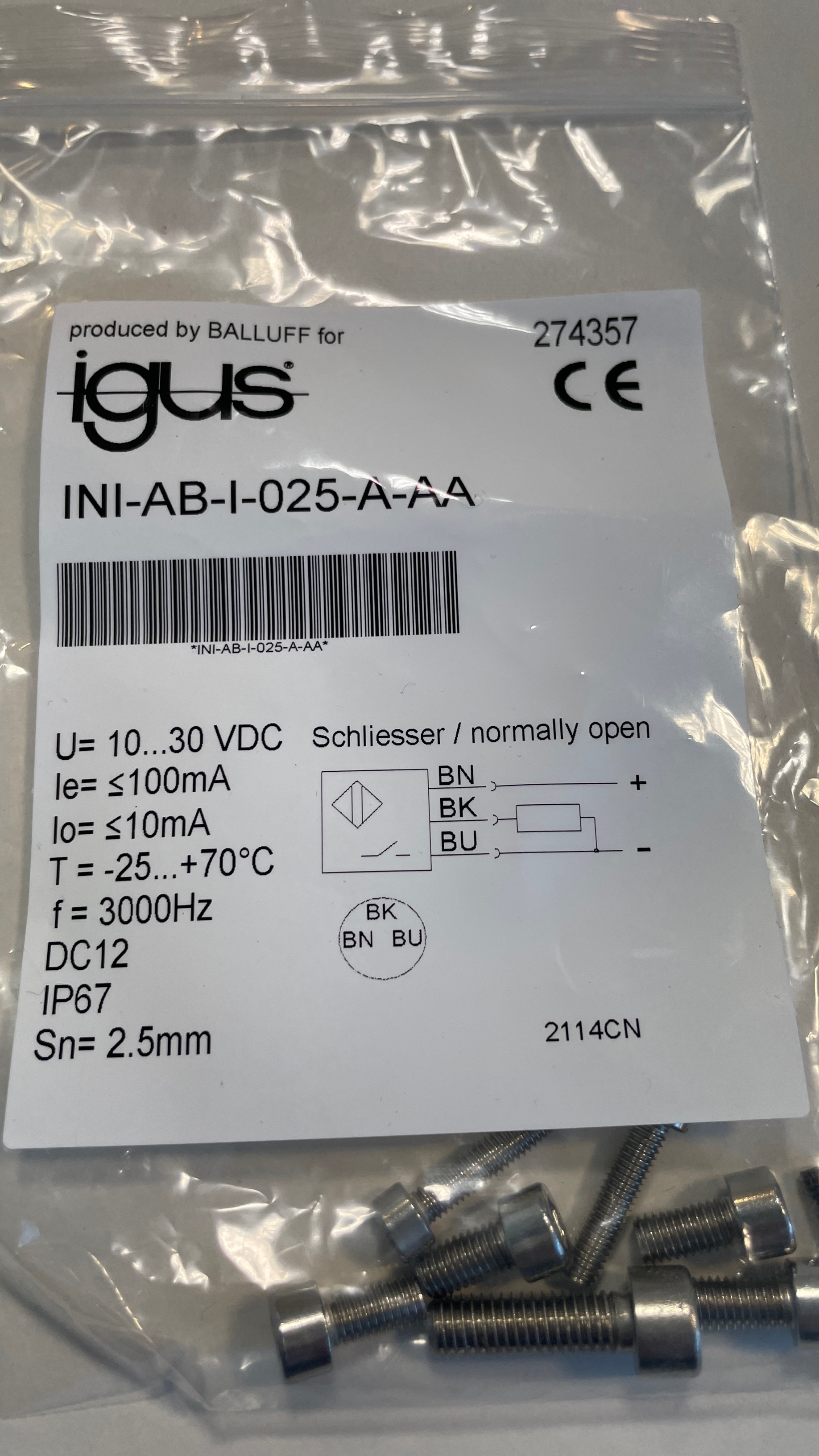
                                I have got this, Is it PNP or NPN?

                                If it is PNP, how do I connect it to the duet board.

                                neo0204undefined 1 Reply Last reply Reply Quote 0
                                • neo0204undefined
                                  neo0204 @neo0204
                                  last edited by

                                  @neo0204 Confirmed it from igus documents, it's PNP.

                                  Screenshot 2021-05-19 at 3.08.23 PM.png

                                  Please help me on how to connect this.

                                  dc42undefined 1 Reply Last reply Reply Quote 0
                                  • dc42undefined
                                    dc42 administrators @neo0204
                                    last edited by

                                    @neo0204 see https://duet3d.dozuki.com/Wiki/Connecting_a_Z_probe?revisionid=HEAD#Section_PNP_output_normally_open_inductive_or_capacitive_sensor.

                                    Duet WiFi hardware designer and firmware engineer
                                    Please do not ask me for Duet support via PM or email, use the forum
                                    http://www.escher3d.com, https://miscsolutions.wordpress.com

                                    neo0204undefined 1 Reply Last reply Reply Quote 0
                                    • neo0204undefined
                                      neo0204 @dc42
                                      last edited by

                                      @dc42 Thank you, I will try this.

                                      1 Reply Last reply Reply Quote 0
                                      • First post
                                        Last post
                                      Unless otherwise noted, all forum content is licensed under CC-BY-SA