Syringe endstop
-
Hello everybody,
I am absolutely stuck in understanding how to do too many things, and I have so many open fronts that I have chosen to solve each one separately; dense posts full of questions are not well received.
- Extruder endstop:
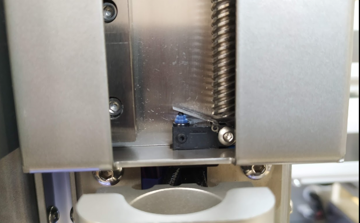
One of the printhead tools is a syringe. We have put a physical endstop at the bottom to detect that the syringe has run out, it is NO endstop and physically connected to the pin "21.io0.in"
The pin apparently works, we set as:
; External triggers
M950 J1 C "21.io0.in"; endstop gel toolhead
M581 T1 P1 S1 R0; endstop gel
Pressing it resets the controller when the M581 T0 option is present, so it phisically works. With T1 it would supposedly call a trigger1?
We have created the trigger1.g file so that it pauses the printer immediately after the activation of that endstop occurs, but we do not see it execute.
; trigger1.g: trigger for GPIO endstop gel toolhead
M25; pause print
M83; relative position
G1 E-5 F500
What we need is: the printer could be paused when it detects that their endstop has been activated, and during the pause it allows the extruder to be moved backwards or forwards manually with the retract/extrude buttons from DWC to insert a new full syringe, to be able exact purge it, and after doing all this, we could press continue button and retake where we left off.
This, which should be very easy, is messy. I don't want to imagine the rest that we have left to do and how steep is being the incursion in RRF.
- Extruder endstop:
-
@marcossf Trigger1 is a system defined trigger. Use Trigger2 or higher. See https://duet3d.dozuki.com/Wiki/Gcode#Section_M581_RepRapFirmware_3_01_and_later
Trigger number 1 causes the print to be paused as if M25 had been received. Any trigger number # greater than 1 causes the macro file sys/trigger#.g to be executed.
Ian
Bed-slinger - Mini5+ WiFi/1LC | RRP Fisher v1 - D2 WiFi | Polargraph - D2 WiFi | TronXY X5S - 6HC/Roto | CNC router - 6HC | Tractus3D T1250 - D2 Eth
-
@droftarts Ok, i'll test it renaming to T2.
Do you think is the right way how we are doing it?
Thanks!
-
Ok, renamed to 2 and tested.
If I send M582 T2 the trigger2.g is executed (back 5mm the syringe extruder). Also It doesn't pause when printing.
If send a extrude movement and push the endstop, nothing stops, but when release it execute the trigger2 sequence. The same when printing.
Maybe could not pause in the middle of a G1 movement? The endstop has a 1mm from trigger position to phisical axis limit, so a 1mm hysteresis when triggered would be feasible. Ideal would be break and pause inmediatelly at trigger position.
-
@marcossf said in Syringe endstop:
If send a extrude movement and push the endstop, nothing stops, but when release it execute the trigger2 sequence. The same when printing.
I think you have this set:
M581 T1 P1 S1 R0; endstop gelS parameter: Whether trigger occurs on an inactive-to-active edge of that input (S1, default), active-to-inactive edge (S0), or ignores that input (S-1). By default, all triggers ignore all inputs.
How is your endstop wired? Is it NO? If so, either change S parameter to S0, or wire the microswitch NC, or invert the input in M950 (ie make it
C "!21.io0.in".Ian
Bed-slinger - Mini5+ WiFi/1LC | RRP Fisher v1 - D2 WiFi | Polargraph - D2 WiFi | TronXY X5S - 6HC/Roto | CNC router - 6HC | Tractus3D T1250 - D2 Eth
-
@droftarts The relevant lines we have in config.g are:
;Endstop
M574 T2 S0 P"21.io0.in"	      ; configure endstop for low end on GEL via pin 21.io0.in
;Triggers M950 J1 C"21.io0.in" ;endstop gel toolhead M581 T2 P1 S0 R0 ;endstop gelTried with S0 or S1 in both sections, inverted pin(!) or not. The endstop is NO, can't be changed to NC (Omrom D2HW-C213MR)
When triggered the switch the E motor execute the trigger2.g file, while printing or not; but never pause, and waits to movement end to do the trigger2 instructions. This is the test gcode to see activation:
; test print for E-Endstop
G28	;home
G1 Y-125 f2000 ;put Y at front
T1	;select gel tool
M302 P1	;allow cold extruder
G90	;absolute movement
G92 E0	;reset extrusor position
G1 E2 f100	;some positive movement
G1 E5 f100	;more positive movement
G1 E20 F100	;much more positive movement
G1 E-20 F100	;retract to test inverse endstop activation
G1 Y0 f2000	;move Y back to middle to indicate end of movement.
When printing this gcode, in console can be seen that the trigger is done after finish, retracting the 5mm that are defined in trigger2.g and the pause doesn't execute, because it's already ended (its small code and eaten by the buffer). So the endstop it isn't pausing or interrupt the Gcode stream.
14/7/2021 19:29:05	Finished printing file 0:/gcodes/prueba e-endstop.gcode, print time was 0h 1m
Error: Cannot pause print, because no file is being printed!
14/7/2021 19:27:56	M32 "0:/gcodes/prueba e-endstop.gcode"
File 0:/gcodes/prueba e-endstop.gcode selected for printing
How i can see in realtime the status of this GPIO pin? Endstop It isn't present at M119.
-
-
@o_lampe How impact this segmentation have in performance, precision or quality?
Everyone using a syringe or paste extruder have this problem? How stop the syringe when empty?
After some tests, the endstop has been broken because the motor smash it at lower limit without stop it. Today i will replace it and leave for manually activate outside the extruder assembly until a repeatable pause behaviour can be achieved.
I dig the forum and saw several people who did it, I don't know where's our fault.
Whould be better define the tool extruder as an axis with their endstop that stops the movement instead a trigger?
-
@marcossf why not configure that endstop as a filament monitor?
I suggest you design that endstop so that it triggers a little before the syringe is empty and allows for some further movement of the syringe after triggering. Then you won't need an instant response to it.
Duet WiFi hardware designer and firmware engineer
Please do not ask me for Duet support via PM or email, use the forum
http://www.escher3d.com, https://miscsolutions.wordpress.com -
@dc42 Hi David,
I've tested @o_lampe suggestions and it's viable. The M669 K0 S100 segmentation make it much responsive the trigger. I don't know if this segmentation could have impact in other areas.
Now, the endstop can be detected much fast. However, we will also try to do it with the M600 in case we obtain a better or more adjusted behavior.
The reason we need a fast trigger is because the syringe is very small (2 mililiters), and they will use extremely expensive dispensing materials so less errors/null extrusions saves money.
The working code so far is:
M669 K0 S100						; cartesian kinematics and segments per second

M574 T2 S1 P"21.io0.in"			; configure endstop for low end on GEL via pin 21.io0.in

M950 J1 C"21.io0.in"				;endstop gel toolhead
M581 T2 P1 S0 R0				;endstop gel T2=trigger2-g
Also i've tested move back the extruder while the pause it's active to accommodate a new syringe and it works.
Now, I have to see how to distinguish a normal pause (M25) from a pause triggered by the syringe endstop, since the normal pause should not execute the trigger2.g script.
-
@marcossf if you configure it as a filament monitor then it will run filament-error.g instead of pause.g.
Duet WiFi hardware designer and firmware engineer
Please do not ask me for Duet support via PM or email, use the forum
http://www.escher3d.com, https://miscsolutions.wordpress.com -
@dc42 Ok, this afternoon I will test with the M600.
I'm thinking that there's also another advantage if use M600, that would been easier to make the macro independent from other toolheads.
-
@marcossf do not use M600. That is for commanding a filament change from within a GCode file. Look up M591.
If you have multiple tools, each can have its own macro file. For example, if the filament monitor for extruder 0 reports an error, RRF will try to run filament-error0.g, failing that filament-error.g, failing that pause.g.
Duet WiFi hardware designer and firmware engineer
Please do not ask me for Duet support via PM or email, use the forum
http://www.escher3d.com, https://miscsolutions.wordpress.com -
@dc42 Ok, i'll try this way
-
@dc42 I've comented the config.g from M581 and endstop configuration for extruder, and added just the M591 like so:
M591 D1 P1 C"21.io0.in" S1I've also renamed the trigger2.g to filament-error.g and remove the M25 from it.
Asked their status with M591 D1, shows its level as expected when activated and release:
Simple filament sensor on pin 21.io0.in, enabled, output low when no filament, filament present: no
Simple filament sensor on pin 21.io0.in, enabled, output low when no filament, filament present: yes
It works fine, but it's more slow than trigger it with the M581 method. After the message apears that has been paused, it still keep moving down the extruder motor to the endstop a few space, despite the pause. The segmentation is in 100.
Config.g:
; Configuration file for Duet 3 (firmware version 3) ; executed by the firmware on start-up ; ; generated by RepRapFirmware Configuration Tool v3.2.3 on Fri Mar 26 2021 17:48:23 GMT+0100 (hora estándar de Europa central) ; General preferences M552 S1 ; ethernet activation M586 P0 S1 ; enable HTTP M586 P1 S1 ; enable FTP M586 P2 S1 ; enable Telnet G90 ; send absolute coordinates... M83 ; ...but relative extruder moves M550 P"Duet 3" ; set printer name G4 S3 ; wait for expansion boards to start M669 K0 S100 ; cartesian kinematics and segments per second ; Drives M569 P40.0 S1 ; physical drive 40 goes forwards X M569 P41.0 S0 ; physical drive 41 goes forwards Y1 M569 P42.0 S0 ; physical drive 42 goes forwards Y2 M569 P43.0 S0 ; physical drive 43 goes backwards Z1 (Z) M569 P44.0 S0 ; physical drive 44 goes backwards Z2 (U) M569 P45.0 S0 ; physical drive 45 goes backwards Z3 (V) M569 P20.0 S1 ; physical drive 20 goes forwards E0 M569 P21.0 S1 ; physical drive 21 goes forwards E1 M569 P22.0 S1 ; physical drive 22 goes forwards E2 M584 X40.0 Y41.0:42.0 Z43.0 U44.0 V45.0 E20.0:21.0:22.0 ; set axis drive mapping M350 X1 Y1 V1 Z1 U1 V1 E16:16:16 I1 ; configure microstepping with interpolation M92 X150.53 Y150.53 Z100.12 U100.12 V100.12 E409.00:420.00:420.00 ; set steps per mm M566 X900.00 Y900.00 Z500.00 U500.0 V500.0 E120.00:120.00:120.00 ; set maximum instantaneous speed changes (mm/min) M203 X18000.00 Y18000.00 Z12000.00 U12000.00 V12000.00 E1200.00:1200.00:1200.00 ; set maximum speeds (mm/min) M201 X500.00 Y500.00 Z500.00 U500.00 V500.00 E250.00:250.00:250.00 ; set accelerations (mm/s^2) M906 E1000:1000:1000 I30 ; set motor currents (mA) and timeout time M84 S30 ; Disable motor idle current reduction ; Axis Limits M208 X-200 Y-125 Z0 U0 V0 S1 ; set axis minima M208 X200 Y125 Z100 U100 V100 S0 ; set axis maxima ; Endstops M574 X1 S1 P"!40.io0.in" ; configure active-high endstop for low end on X via pin 40.io0.in M574 Y1 S1 P"!41.io0.in" ; configure active-high endstop for low end on Y via pin 41.io0.in ;M574 Z1 S2 P"!43.io0.in" ; configure active-high endstop for high end on Z via pin 43.io0.in M574 U2 S1 P"!44.io0.in" ; configure active-high endstop for high end on U via pin 44.io0.in M574 V2 S1 P"!45.io0.in" ; configure active-high endstop for high end on V via pin 45.io0.in ;M574 T2 S1 P"21.io0.in" ; configure endstop for low end on GEL via pin 21.io0.in M574 Z1 S2 ; configure Z-probe endstop for low end on Z ; Z-Probe M950 S0 C"out4" ; create servo pin 0 for solenoid on Out4 M558 P8 C"io3.in" H1 R6.5 F1200 T3000 ; set Z probe type and the dive height + speeds G31 X-50 Y55 Z-5 ; set Z probe trigger value, offset and trigger height M557 X-100:100 Y-100:100 S20 ; define mesh grid ; Heaters ; Bed heater M308 S0 P"temp1" Y"thermistor" T100000 B4725 C7.06e-8 ; configure sensor 0 as thermistor on pin temp1 for bed thermistor M950 H0 C"out1" T0 ; create bed heater output on out1 and map it to sensor 0 M307 H0 B0 R0.419 C401.2 D2.65 S1.00 ; disable bang-bang mode for the bed heater and set PWM limit M140 H0 ; map heated bed to heater 0 M143 H0 S100 ; set temperature limit for bed heater 0 to 100C ; Syringe preheater M308 S1 P"temp0" Y"thermistor" T100000 B4725 C7.06e-8 ; configure sensor 1 as thermistor on pin temp0 for syringe preheater M950 H1 C"out0" T1 ; create syringe preheater output on out0 and map it to sensor 1 M307 H1 B0 R0.302 C822.1 D3.84 S1.00 V24.0 ; disable bang-bang mode for the syringe preheater and set PWM limit M141 H1 ; map syringe preheater to heater 1 M143 H1 S130 ; set temperature limit for heater 1 to 130C ; FDM heater M308 S2 P"20.temp0" Y"thermistor" T100000 B4725 C7.06e-8 ; configure sensor 2 as thermistor on pin 20.temp0 (FDM) M950 H2 C"20.out0" T2 ; create nozzle heater output on 20.out0 and map it to sensor 2 M307 H2 B0 R2.131 C224.9 D4.61 S1.00 V23.6 ; disable bang-bang mode for heater and set PWM limit M143 H2 S280 ; set temperature limit for heater 2 to 280C ; GEL heater M308 S3 P"21.temp0" Y"thermistor" T100000 B4725 C7.06e-8 ; configure sensor 3 as thermistor on pin 21.temp0 (GEL) M950 H3 C"21.out0" T3 ; create nozzle heater output on 21.out0 and map it to sensor 3 M307 H3 B0 R0.511 C181.9 D6.18 S1.00 V23.8 ; disable bang-bang mode for heater and set PWM limit M143 H3 S140 ; set temperature limit for heater 3 to 130C ; POWDER Heater M308 S4 P"22.temp0" Y"thermistor" T100000 B4725 C7.06e-8 ; configure sensor 4 as thermistor on pin 22.temp0 (POWDER) M950 H4 C"22.out0" T4 ; create nozzle heater output on 22.out0 and map it to sensor 4 M307 H4 B0 R1.622 C246.4 D5.15 S1.00 V23.9 ; disable bang-bang mode for heater and set PWM limit M143 H4 S175 ; set temperature limit for heater 4 to 170C ; Fans ; Tools M563 P0 S"FDM" D0 H2 F0 ; define tool 0 G10 P0 X-15 Y5 Z3 ; set tool 0 axis offsets G10 P0 R0 S0 ; set initial tool 0 active and standby temperatures to 0C ; M563 P1 S"GEL" D1 H3 F0 ; define tool 1 G10 P1 X-5 Y10 Z4 ; set tool 1 axis offsets G10 P1 R0 S0 ; set initial tool 1 active and standby temperatures to 0C ; M563 P2 S"POWDER" D2 H4 F0 ; define tool 2 G10 P2 X-20 Y15 Z5 ; set tool 2 axis offsets G10 P2 R0 S0 ; set initial tool 2 active and standby temperatures to 0C ; External triggers ;M950 J1 C"21.io0.in" ;endstop gel toolhead ;M581 T2 P1 S0 R0 ;endstop gel T2=trigger2-g M591 D1 P1 C"21.io0.in" S1 ;filament monitor ; Custom settings are not defined -
@dc42 After some Gcode print test with the option of filament sensor looks fine. Real extrusion is more sensible to the stop because extruder movement is fragmented and stops almost inmediatelly.
For the moment we take this point solved and we turn to focus on the offsets and all the other configuration problems that we have.
My principal concern with this method is that it work only when the file is printed from SD. Correct?
At this moment the DUET 6HC is in standalone mode for the machine config development, but the final client printer will store their gcode files in a Repetier Server frontend in a Raspberry Pi (*)
(*)We are still working on making the Duet and Repetier Server share SBC mode from the same RPI and keeping the two interfaces (RS and DWC) on different ports of the same IP and communicating bi-directionally with each other. Repetier is near to have a beta SBC version image to test it.
-
@marcossf said in Syringe endstop:
For the moment we take this point solved
Glad to hear it, but if you want to try a different approach later: I think you can also 'calculate' the amount of material you've used.
- you know the volume of a full syringe
- you know the diameter of the syringe
- you can get the momentary position of the syringe/extruder motor from the object model
Based on these numbers you are able to calculate how much material is left in the syringe and plan ahead, when you have to change tool.
No need to use unreliable switches. -
@o_lampe Yes, it's an option we thought about. Also thought doing it sensorless but the small movement of these axis and low speed we concern about stall detection.
This aproach would need to construct an array of values and conditionals we still don't know how to do.
The syringes are between 2ml to 20ml and use the same push/pull plunger and share only the bottom position because each are different size. At this position it's where located the e-endstop switch.
Still a LOT of things to do so far and we are learning at same time.
")
-
@marcossf you will find that using Repetier server or any other GCode sender except Duet Control Server, a pause will take longer to be actioned. This is because standard GCode protocol doesn't provide any means to stop processing GCode commands already sent to the controller board and then resume them from the same place. Whereas when printing from SD card, moves in the movement queue are tagged with their file offset so that when moves are abandoned due to pausing, the file can be restarted from the correct point. Likewise, when printing through Duet Control Server, the Duet reports to DCS the point at which moves were abandoned so that DCS can restart from the correct point.
Duet WiFi hardware designer and firmware engineer
Please do not ask me for Duet support via PM or email, use the forum
http://www.escher3d.com, https://miscsolutions.wordpress.com -
@dc42 Yes, I understand David. It is something with which we will have to find the balance point.
Ideally, DWC would have all the functionalities that we can have with Repetier Server, which are quite a few. In fact we would like to mantain the standard DWC frontend for tech support, but final customer only need to see what it's relevant for their unskilled task.
We would have to do a totally scratch development to have a fully functional client frontend under your environment, which at this time is not possible due to time and lack of enough human resources. We have urged our developers to learn all this stuff, which is new to all of us, but customers don't want to wait for our learning curve.
We did it for Marlin FW printers and Repetier Server (web and touch UI tailor-made for this type of user).
There are items that I don't even know if it would be possible to get, as authentication and user permissions, network control panel (wifi/cable/domains/IP manual configuration...), print history and reports, white label touchscreen UI customization...that we did in Repetier Server.We are just starting with RRF and Duet3D; and rise up our knowledge with this very first machine, but we expect to get the expertise to have all the client requests fullfilled in the future with this ecosystem, because it has proven to be more flexible than Marlin at this moment plus the Duet hardware quality.
Meanwhile, we will continue to annoy asking questions that are surely very obvious to all of you. We appreciate your help