Moving individual motors of a multi-motor axis to skew-correct
-
Hi,
There's a good chance I'm missing something obvious or this has been asked and my searches just haven't pinpointed it so if that's the case please let me know.
I've just set up my dual motor Z to use independent drivers for the two motors and independent end stops, as per the instructions here. This all works as expected (woohoo!).
However I'm a little suspicious that my end stops may be a bit offset so the X axis would not be perpendicular to the Z. I've also hard-mounted the end stops and their buffers to avoid any position creep associated with the adjustable screw Z fine-tuning design.
As such what I would like to do is move either of the drives (E1/4 or Z/2) independently by a manually measured offset distance during homing to bring them in sync with each other. Pseudo code as follows:Home Z ; as per standard Move left (or right) Z motor by [n]mm ; offset one side to compensate skew Set Z height as 0 ; ensure new compensated alignment is recognised as homed and levelHow do I address the individual motor of the pair to move it?
Thanks for the help

-
@samanthajaneycake I'm assuming you have a bed-flinger that lifts the X axis with a pair of Z screws, similar to a Prusa printer. You really don't need two endstops and to drive the motors independently to correct the X axis tilt relative to Z. Just do what Prusa does- send the X axis to the top of the machine (actually a little beyond the top) until it hits the mechanical stops which you have already positioned to force the X axis perpendicular to the Z axis.
-
@mrehorstdmd And say I'd rather have full control over this than trusting the top bar? Having done that before I can safely say it won't help correct skew.
-
@samanthajaneycake It seems to work fine for correcting XZ skew in the Prusa machines...
-
@mrehorstdmd Be that as it may this is off-topic. I'm hoping someone can help me out with this specific issue and not the more broad scope of printer design, of which mine is rather custom and best known by me.
Thank you for your input. -
@samanthajaneycake
I did this in RRF3 under the assumption that there’s a command that will allow me to address individual drivers regardless of a “synced” status. After all, when homing with 2 Z min end stops they act individually, so the command must exist.I’m wondering if I need to temporarily split Z into Z and U axes and if that’s the case do I need to set up U in config essentially the same as how it’s done in RRF2.x?
Am I just over complicating this by trying to find a RRF3 method for what works in RRF2.x?
-
@samanthajaneycake said in Moving individual motors of a multi-motor axis to skew-correct:
I’m wondering if I need to temporarily split Z into Z and U axes and if that’s the case do I need to set up U in config essentially the same as how it’s done in RRF2.x?
Correct. If you want to control a motor individually you must map it to it's own axis.
The combined endstop homing in RRF3 is for convenience sake since most of the time you just want to home the axis to the endstop and the endstop points are assumed to be correct. This would remove the skew. However, if your endstops aren't in the "correct" position, you're back to needed to move the drives independently. So either fix the endstop positions, or take full control of the motors.
-
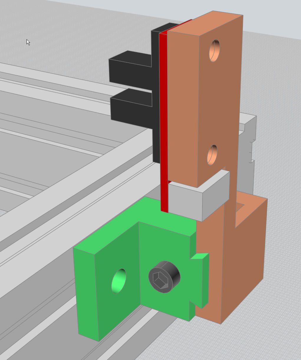
I just created mounts for my IR beam break endstop sensors that were adjustable via a M3 machine screw.
It was very easy to get them in exactly the right position so "normal" homing using an endstop sensor for each stepper on the X or Y axis.
Printers: a small Utilmaker style, a small CoreXY and a E3D MS/TC setup. Various hotends. Using Duet 3 hardware running 3.4.6
-
@phaedrux Thank you for your reply, that clarified things. I'll implement RRF2.x methodology tonight after work.
P.S. How do I flag as solved?
-
@fcwilt (warning: ramble incoming) My printer is an own-design foldable bedslinger so has a few frame and component quirks compared to commercial units. It was foldable because at the time I was a student and moved around a fair bit. Having a printer I could fold down and pick up by the handle like a suitcase was very handy.
I designed and built it back in 2015 when having a screw on one Z carriage and an end stop positioned below it was the "way it was done". I did not want to reprint and reassemble the rightmost Z carriage with its own screw especially as I am not a huge fan of having 2 adjustment points for Z: Z carriage offset and bed height. If the Z carriages are at the same and correct height (and thus X is perpendicular to Z) then the bed can be trammed to that without issue. To my mind it's more important that Z and X be perpendicular then bed trammed in accordance than adjusting Z to match the bed.
So having decided I do not like the Z end stop screw adjustment method (and given the fact that due to some long-forgotten design decisions I have 2x end stop mounts but not 2x end stop screw mounts) it made sense to remove the screw, glue on a pair of buffers to the Z carriages and mount the second end stop. 10 minutes design, 30 minutes print, 30 minutes gluing, soldering, crimping and plugging.
At some point I may take the time to go through the entire build and redesign it to smooth out any issues I've encountered in the past 4-5 years but this was a simple and cheap improvement.