Duet3D Logo

    Duet3D

    • Register
    • Login
    • Search
    • Categories
    • Tags
    • Documentation
    • Order

    Solved [F407ZG] How to activate endstop power?

    STM
    f407zg
    2
    3
    108
    Loading More Posts
    • Oldest to Newest
    • Newest to Oldest
    • Most Votes
    Reply
    • Reply as topic
    Log in to reply
    This topic has been deleted. Only users with topic management privileges can see it.
    • o_lampe
      o_lampe last edited by o_lampe

      Hi guys,
      how do I activate the row of endstops on the 407ZG? I had to tap 3.3V from another header to make my IR-beam brakers work.
      As a sidenote: the endstops were named 'xstop' and 'ystop' from the STM-config tool, but there are 'xmin/xmax' headers...
      P.S. Where can I find a better pin mapping chart? The picture on the 'pin names' page is almost unreadable...

      jay_s_uk 1 Reply Last reply Reply Quote 0
      • jay_s_uk
        jay_s_uk @o_lampe last edited by jay_s_uk

        @o_lampe there is a header here
        5de96294-452e-49cb-91f1-63b53e47e9ed-image.png
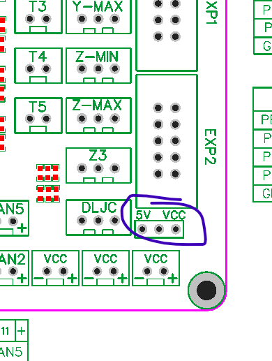
        This enables 5v or VCC (12v or 24v) at the end stops.
        Either name is accepted for each endstop input, e.d. xmax or xstopmax.
        We standardised on xstop and xstopmax etc across boards so config's can easily be moved.
        The image on the pins page is SVG and can be opened in a new tab to view it larger

        Owns various duet boards and is the main wiki maintainer for the Teamgloomy LPC/STM32 port of RRF. Assume I'm running whatever the latest beta/stable build is

        o_lampe 1 Reply Last reply Reply Quote 0
        • o_lampe
          o_lampe @jay_s_uk last edited by

          @jay_s_uk Thanks Jay, I missed that info on the github pages...

          1 Reply Last reply Reply Quote 0
          • First post
            Last post
          Unless otherwise noted, all forum content is licensed under CC-BY-SA