Large Format Dowell to Duet conversion
-
Also the output of the heater for the heated bed goes to a relay. The polarity of the wires seems to matter but I can’t work out which of the pins on ‘OUT0’ on the 3HC is positive or negative. Sorry if this should be possible to determine from the wiring diagram, I still can’t work that out after looking at it


Please NB location of blue and brown wires.
-
@charles-fraser said in Large Format Dowell to Duet conversion:
M98 P"0:/sys/config.g" it just posts that in the event log in a green coloured entry. Nothing else comes back.
Thats good, means there are no commands that are erroring when the machine starts
edited to refer to the table you shared here:
https://docs.google.com/spreadsheets/d/1BnwMvK9tU8W356t2_NAa4YQPk077nXfBA7ScrNfxe_A/edit#gid=0I have only started covering the issues - I can't answer your questions if you ask them quicker than I can answer - 1 step at a time.
I am assuming that the wiring is plugged in as that table refers except the BL touch which is potentially faulty as was preventing the expansion board form starting up. First check there are still no issues with communication or safety after everything is plugged (send M122, M122 B1, check no heaters are heating uncontrollably).
- You have the table showing a Thermocouple being used for the heated bed, connected to thermocouple DB that is plugged into the 3HC. The heater for the heated bed is controlled by a SSR from the 3HC. That should be ok, although the configuration is set to have it connected to the mainboard so lets change that:
M308 S0 P"1.spi.cs0" Y"thermocouple-max31855" ; configure sensor 0 as thermocouple via CS pin 1.spi.cs1 on expansion board 1
M950 H0 C"1.out2" T0                                              ; create bed heater output on expansion board 1 out2 and map it to sensor 0
Cross reference with the 6HC wiring diagram here:
https://duet3d.dozuki.com/Wiki/Duet_3_Mainboard_6HC_Wiring_Diagram
and 3HC wiring diagram here:
https://duet3d.dozuki.com/Wiki/Duet_3_Expansion_3HC_Wiring_Diagram- Similar to point 1, the config does not match your table, change it to:
M308 S1 P"1.temp1" Y"thermistor" T100000  B3800                              ; configure sensor 1 as PT1000 on pin temp0
M950 H1 C"1.out1" T1                                              ; create nozzle heater output on out2 and map it to sensor 1
For some reason you had a PT1000 set in the config, not a thermistor so check that. NOTE the B value in the line above is probably totally wrong as it will be specific to the thermistor. you need to find out what the correct B (and C if the manufacture gives that) values you should be using for this specific thermistor.
-
Fans. Your config has the hotend cooling fan connected to out 8 on the mainboard and the part cooling fan connected to out9. that will be fine if they are both 2 wire fans that run at the same voltage. and fan 1 is your hotend cooling fan, while fan 2 is your part cooling fan.
-
Your table does not match the wiring diagram for motors, You only have 1 Z motor defined and 4 extruders. The table has the following setup:
z back right Driver 3
z front right Driver 2
x Driver 0
y Driver 1
z front left Driver 4
z back left Driver 5
Extruder motor Expansion Driver 0
Note, refer to the mainboard 6HC wiring diagram again - can you confirm that is how you have them plugged in because an earlier image you posted with a schematic had them plugged in differently. Check where each driver is on the mainboard!
The M584 command needs adjusting to correctly assign the driver to the correct axis (assuming the mapping as you have in the table):
M584 X0.0 Y0.1 Z0.2:0.4:0.5:0.3 E1.0This sets the order of the Z motors as Front right, Front left, back left, back right. which is important for Z levelling later.
You also need to adjust the subsequent commands to take into account you have 4 Z motors and 1 extruder.M350 X16 Y16 Z16 E16 I1 ; configure microstepping with interpolation M92 X80.00 Y80.00 Z400.00 E420.00 ; set steps per mm M566 X900.00 Y900.00 Z60.00 E120.00 ; set maximum instantaneous speed changes (mm/min) M203 X6000.00 Y6000.00 Z180.00 E1200.00 ; set maximum speeds (mm/min) M201 X500.00 Y500.00 Z20.00 E250.00 ; set accelerations (mm/s^2) M906 X3000 Y3000 Z800 E800 I30 ; set motor currents (mA) and motor idle factor in per centNote for now I have just removed the additional extruder parameters. The settings there will apply equally to all Z motors which I assume are the same.
- The co ordinates for you motors (for use in M671 later in the process). I think they are as follows based on the image you have posted:
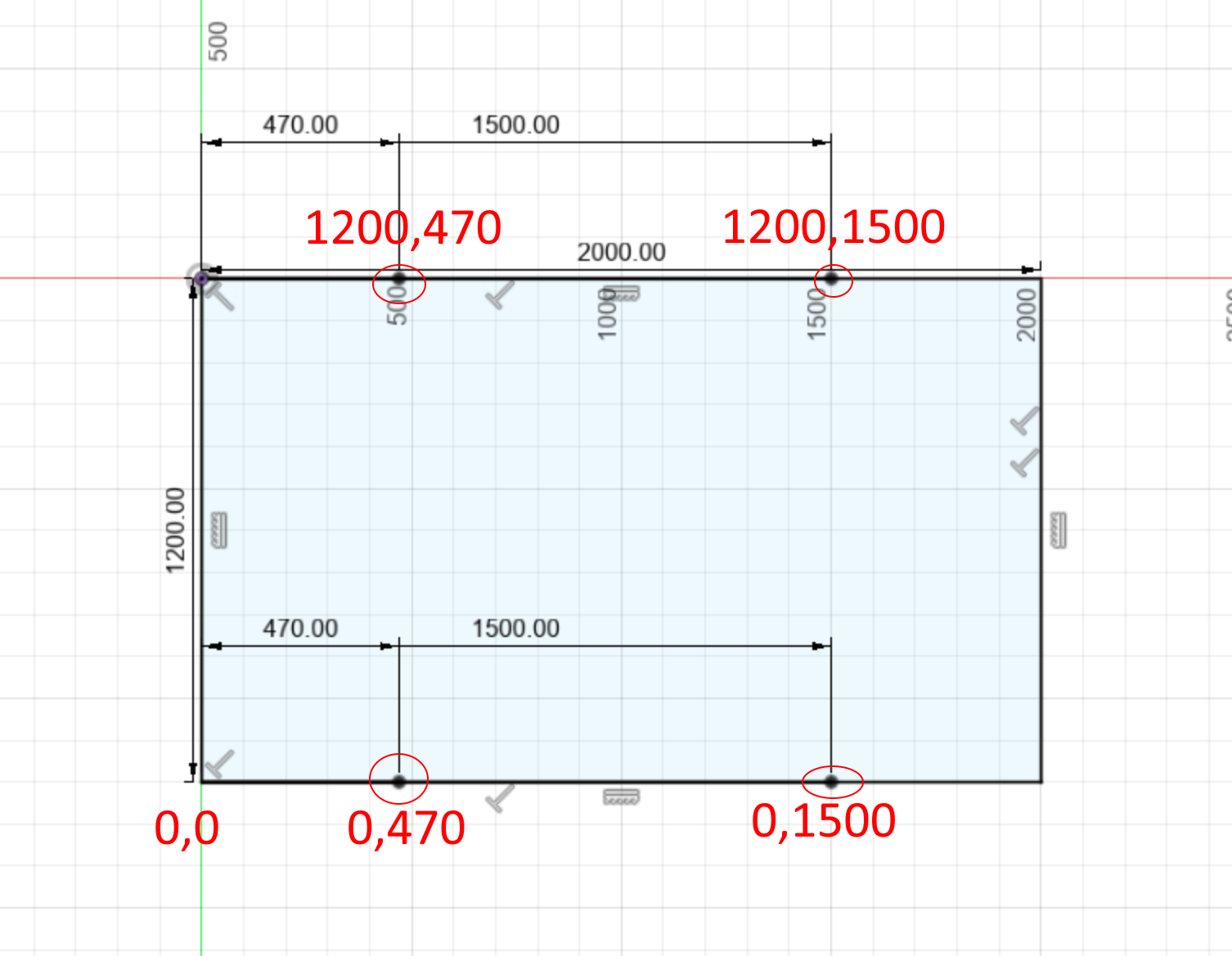
Assuming the motors are where the circles are?
Ok I think that is enough for now. Make the changes to config.g I have suggested and then re-run M98 P"0:/sys/config.g". Then plost config.g here again and we can take the next steps.
-
you are amazing Tony thank you so much! I need to get inside to warm up abit and cook supper then will get outside again to give it some more work. Thank you thank you thank you!
-
Thanks so much Tony! So:
- M122 under heaters says
=== Diagnostics ===
RepRapFirmware for Duet 3 MB6HC version 3.3 (2021-06-15 21:45:47) running on Duet 3 MB6HC v1.01 or later (SBC mode)
Board ID: 08DJM-9P63L-DJ3S0-7J1D6-3SD6S-1UJV8
Used output buffers: 1 of 40 (13 max)
=== RTOS ===
Static ram: 150904
Dynamic ram: 61572 of which 0 recycled
Never used RAM 141716, free system stack 202 words
Tasks: SBC(ready,4.9%,306) HEAT(delaying,0.0%,351) Move(notifyWait,0.0%,352) CanReceiv(notifyWait,0.0%,908) CanSender(notifyWait,0.0%,374) CanClock(delaying,0.0%,339) TMC(notifyWait,7.3%,93) MAIN(running,87.7%,1252) IDLE(ready,0.0%,29), total 100.0%
Owned mutexes: HTTP(MAIN)
=== Platform ===
Last reset 00:09:13 ago, cause: power up
Last software reset at 2021-10-06 17:48, reason: User, none spinning, available RAM 141716, slot 1
Software reset code 0x0012 HFSR 0x00000000 CFSR 0x00000000 ICSR 0x0044a000 BFAR 0x00000000 SP 0x00000000 Task SBC Freestk 0 n/a
Error status: 0x00
Step timer max interval 129
MCU temperature: min 25.2, current 31.6, max 31.9
Supply voltage: min 24.1, current 24.2, max 24.2, under voltage events: 0, over voltage events: 0, power good: yes
12V rail voltage: min 12.2, current 12.2, max 12.2, under voltage events: 0
Heap OK, handles allocated/used 0/0, heap memory allocated/used/recyclable 0/0/0, gc cycles 0
Driver 0: position 0, standstill, reads 16623, writes 14 timeouts 0, SG min/max 0/0
Driver 1: position 0, standstill, reads 16623, writes 14 timeouts 0, SG min/max 0/0
Driver 2: position 0, standstill, reads 16623, writes 14 timeouts 0, SG min/max 0/0
Driver 3: position 0, standstill, reads 16623, writes 14 timeouts 0, SG min/max 0/0
Driver 4: position 0, standstill, reads 16623, writes 14 timeouts 0, SG min/max 0/0
Driver 5: position 0, standstill, reads 16623, writes 14 timeouts 0, SG min/max 0/0
Date/time: 2021-10-06 20:51:18
Slowest loop: 0.46ms; fastest: 0.06ms
=== Storage ===
Free file entries: 10
SD card 0 not detected, interface speed: 37.5MBytes/sec
SD card longest read time 0.0ms, write time 0.0ms, max retries 0
=== Move ===
DMs created 125, maxWait 0ms, bed compensation in use: none, comp offset 0.000
=== MainDDARing ===
Scheduled moves 0, completed moves 0, hiccups 0, stepErrors 0, LaErrors 0, Underruns [0, 0, 0], CDDA state -1
=== AuxDDARing ===
Scheduled moves 0, completed moves 0, hiccups 0, stepErrors 0, LaErrors 0, Underruns [0, 0, 0], CDDA state -1
=== Heat ===
Bed heaters = 0 -1 -1 -1 -1 -1 -1 -1 -1 -1 -1 -1, chamberHeaters = -1 -1 -1 -1
=== GCodes ===
Segments left: 0
Movement lock held by null
HTTP* is doing "M122" in state(s) 0
Telnet is idle in state(s) 0
File is idle in state(s) 0
USB is idle in state(s) 0
Aux is idle in state(s) 0
Trigger* is idle in state(s) 0
Queue is idle in state(s) 0
LCD is idle in state(s) 0
SBC is idle in state(s) 0
Daemon is idle in state(s) 0
Aux2 is idle in state(s) 0
Autopause is idle in state(s) 0
Code queue is empty.
=== CAN ===
Messages queued 4902, received 7, lost 0, longest wait 1ms for reply type 6042, peak Tx sync delay 333, free buffers 49 (min 48), ts 2769/2768/0
Tx timeouts 0,0,0,0,0,0
=== SBC interface ===
State: 4, failed transfers: 1, checksum errors: 0
Last transfer: 1ms ago
RX/TX seq numbers: 18779/18925
SPI underruns 0, overruns 0
Disconnects: 1, timeouts: 0, IAP RAM available 0x2c810
Buffer RX/TX: 0/0-0
=== Duet Control Server ===
Duet Control Server v3.3.0
Code buffer space: 4096
Configured SPI speed: 8000000Hz
Full transfers per second: 19.81, max wait times: 8.6ms/0.0ms
Codes per second: 0.00
Maximum length of RX/TX data transfers: 3203/64
M122 B1 Says
Diagnostics for board 1: Duet EXP3HC firmware version 3.3 (2021-06-15 16:12:41) Bootloader ID: not available Never used RAM 159072, free system stack 4400 words Tasks: Move(notifyWait,0.0%,160) HEAT(delaying,0.0%,104) CanAsync(notifyWait,0.0%,69) CanRecv(notifyWait,0.0%,82) CanClock(notifyWait,0.0%,71) TMC(notifyWait,7.2%,63) MAIN(running,91.5%,430) IDLE(ready,0.0%,39) AIN(delaying,1.3%,263), total 100.0% Last reset 00:10:07 ago, cause: software Last software reset data not available Driver 0: position 0, 420.0 steps/mm, standstill, reads 56771, writes 16 timeouts 0, SG min/max 0/0, steps req 0 done 0 Driver 1: position 0, 80.0 steps/mm, standstill, reads 56776, writes 11 timeouts 0, SG min/max 0/0, steps req 0 done 0 Driver 2: position 0, 80.0 steps/mm, standstill, reads 56777, writes 11 timeouts 0, SG min/max 0/0, steps req 0 done 0 Moves scheduled 0, completed 0, in progress 0, hiccups 0, step errors 0, maxPrep 0, maxOverdue 0, maxInc 0, mcErrs 0, gcmErrs 0 Peak sync jitter -2/8, peak Rx sync delay 178, resyncs 0/0, no step interrupt scheduled VIN: 24.0V, V12: 12.2V MCU temperature: min 23.3C, current 24.3C, max 24.7C Ticks since heat task active 193, ADC conversions started 607931, completed 607931, timed out 0, errs 0 Last sensors broadcast 0x00000000 found 0 198 ticks ago, loop time 0 CAN messages queued 31, send timeouts 0, received 5392, lost 0, free buffers 37, min 37, error reg 110069 dup 0, oos 0/0/0/0, bm 0, wbm 0, rxMotionDelay 0- Okay I changed those values for the sensors and heaters (all on the 3HC) thanks!
Juan who designed and built the pellet extruder does not have the thermistor info. It might be easier to just buy a new one that fits in the heating block. Any recommendations would be appreciated re kind.
-
Fans, the fans are 12V fans I think. Both two wire fans running at Q500 which is barely at all but when I change that value up it just makes more noise but doesnt spin much at all.
-
Yea those are the correct driver to motor matches in the table - I changed it from the pic before to try and match the config tool and arrangement in the instructions for setting up multiple z motors. I've added all the config you setup thank you!
4.1 I still need to work out the correct miliAmps for Nema 17 (z motors & extruder motor) and mAmps for Nema 23 X & Y motors.
4.2 I still need to work out the steps per mm info. The screws on the z scres has a lead of 5mm and a toothed gear at the top with a pulley to another toothed gear on the nema 17 motor. I'll add a pic here in a bit. Not sure how to work out what kind of gears they are for the gear ratio calculations / steps / mm cals
4.3 Not sure what microstepping setting to set for best performance / my use case, mostly printing with a 3mm Nozzle
- Okay not sure where to add the M671 command so will wait till later in the process. Thanks for that!
I just saved that config and updated the board. I can see the heater thermistor is at a balmy -273C which I think is pretty close to absolute zero, which is how I feel right now. Bed says n/a
I sent that M98 command and
06/10/2021, 21:29:47	M98 P"0:/sys/config.g"
Error: M308: Unknown sensor type name "thermocouplemax3185"
Warning: M950: Sensor number 0 has not been defined
06/10/2021, 21:27:01	Warning: M950: Sensor number 0 has not been defined
06/10/2021, 21:27:01	Error: M308: Unknown sensor type name "thermocouplemax3185"
The config file now looks like:
; Configuration file for Duet 3 (firmware version 3.3)
; executed by the firmware on start-up
;
; generated by RepRapFirmware Configuration Tool v3.3.3 on Fri Oct 01 2021 16:59:54 GMT+0100 (British Summer Time)

; General preferences
G90                                                             ; send absolute coordinates...
M83                                                             ; ...but relative extruder moves

; Wait a moment for the CAN expansion boards to start
G4 S2


; Drives
M569 P0.0 S1                                                    ; physical drive 0.0 goes forwards
M569 P0.1 S1                                                    ; physical drive 0.1 goes forwards
M569 P0.2 S1                                                    ; physical drive 0.2 goes forwards
M569 P0.3 S1                                                    ; physical drive 0.3 goes forwards
M569 P0.4 S1                                                    ; physical drive 0.4 goes forwards
M569 P0.5 S1                                                    ; physical drive 0.5 goes forwards
M569 P1.0 S1                                                    ; physical drive 1.0 goes forwards
M584 X0.0 Y0.1 Z0.2:0.4:0.5:0.3 E1.0
M350 X16 Y16 Z16 E16  I1                                ; configure microstepping with interpolation
M92 X80.00 Y80.00 Z400.00 E420.00          ; set steps per mm
M566 X900.00 Y900.00 Z60.00 E120.00        ; set maximum instantaneous speed changes (mm/min)
M203 X6000.00 Y6000.00 Z180.00 E1200.00 ; set maximum speeds (mm/min)
M201 X500.00 Y500.00 Z20.00 E250.00        ; set accelerations (mm/s^2)
M906 X3000 Y3000 Z800 E800 I30                      ; set motor currents (mA) and motor idle factor in per cent
M84 S30                                                         ; Set idle timeout

; Axis Limits
M208 X0 Y0 Z0 S1                                                ; set axis minima
M208 X1200 Y2000 Z1600 S0                                       ; set axis maxima

; Endstops
M574 X1 S1 P"io0.in"                                            ; configure active-high endstop for low end on X via pin io0.in
M574 Y1 S1 P"io1.in"                                            ; configure active-high endstop for low end on Y via pin io1.in
M574 Z1 S2                                                      ; configure Z-probe endstop for low end on Z

; Z-Probe
M558 P9 C"^1.io1.in" H100 F120 T6000                            ; set Z probe type to switch and the dive height + speeds
G31 P500 X0 Y0 Z2.5                                             ; set Z probe trigger value, offset and trigger height
M556 S50 X0 Y0 Z0                                               ; set orthogonal axis compensation parameters
M557 X15:215 Y15:195 S20                                        ; define mesh grid

; Heaters
M308 S0 P"1.spi.cs0" Y"thermocouple-max31855" ; configure sensor 0 as thermocouple via CS pin 1.spi.cs1 on expansion board 1
M950 H0 C"1.out2" T0                                              ; create bed heater output on expansion board 1 out2 and map it to sensor 0
M307 H0 B1 S1.00                                                ; enable bang-bang mode for the bed heater and set PWM limit
M140 H0                                                         ; map heated bed to heater 0
M143 H0 S80                                                    ; set temperature limit for heater 0 to 80C
M308 S1 P"1.temp1" Y"thermistor" T100000  B3800                              ; configure sensor 1 as PT1000 on pin temp0
M950 H1 C"1.out1" T1                                              ; create nozzle heater output on out2 and map it to sensor 1
M307 H1 B0 S1.00                                                ; disable bang-bang mode for heater  and set PWM limit
M143 H1 S300                                                    ; set temperature limit for heater 1 to 300C

; Fans
M950 F0 C"out8" Q500                                            ; create fan 0 on pin out8 and set its frequency
M106 P0 S0 H T45                                                ; set fan 0 value. Thermostatic control is turned on
M950 F1 C"out9" Q500                                            ; create fan 1 on pin out9 and set its frequency
M106 P1 S1 H-1                                                  ; set fan 1 value. Thermostatic control is turned off

; Tools
M563 P0 S"lily" D0 H1 F0:1                                      ; define tool 0
G10 P0 X100 Y100 Z0                                             ; set tool 0 axis offsets
G10 P0 R0 S0                                                    ; set initial tool 0 active and standby temperatures to 0C

; Custom settings are not defined
thank you again. I hope you are researching the very finest Welsh ales you want for Christmas
-
@charles-fraser right. the error with thermocouple board is because i copied what was already in the config and looking back at the picture you have a newer TC board so it should be the following line
M308 S0 P"1.spi.cs0" Y"thermocouple-max31856"
I hope that fixes that issue.
For the hotend thermistor - even if the B value is wrong we should still get some sort of reading. (not -273). Looking back at old pics in this thread it looks like you have it plugged into Temp0, not Temp1 so either switch it to Temp1 on the board, or change the config to point to Temp0.
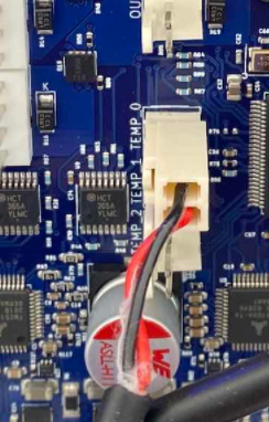
M308 S1 P"1.temp0" Y"thermistor" T100000 B3800 ; configure sensor 1 as thermistor on pin temp0Onto the next point:
Also the output of the heater for the heated bed goes to a relay. The polarity of the wires seems to matter but I can’t work out which of the pins on ‘OUT0’ on the 3HC is positive or negative. Sorry if this should be possible to determine from the wiring diagram, I still can’t work that out after looking at it
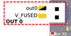
the pin labelled "out0" is the negative. The pin labelled V_FUSED is the fused VIN voltage (24V in your case).I could not find the data sheet for that model of relay exactly but found a similar image:
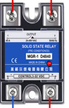
Which shows it can accept upto 32V as the control line so your 24V should be fine. Connect VFUSED to the +'ve side (terminal #3) and out0 to the -;ve side (terminal 4).
So the opposite way around from that you have.Regarding the current for your motors. if you look at the model numbers, find the data sheets, the look at the maximum current. then set it to 70% of that maximum for now.
-
@t3p3tony righto, thanks - I just have a team work session for an hour and a half then will get onto it.
Many thanks, Charles -
Thank you Tony!
- Okay so I changed the thermocouple & thermistor code as described. Sorry about that
After updating the board there is still n/a for the thermocouple and -298C for the thermistor on the nozzle. May I check these settings are both for the 3HC?
-
I swapped the wires in the bed heater around
-
Nema 17s I can't find a data sheet for. This gantry was put together in Shenzen and when I search the name and model number on the z motors (42byg4208-25 jingcheng motor 03303 20-10) or a variation thereof I get nothing of that name. I guess it is a Nema 17 because of the dimentions of the base plate but not sure what to do here other than maybe use some geneic value of a nema17 motor of the same size (40x40x67)

The Nema 23s (x & y axis motors) say 4.aA on the back so 2800mA is 70% of that. For reference below is the model number and here is the data sheet which specifies 5A rating, differing from what is printed on the back of the product.

-
@charles-fraser they are for board id1 which is how your 3hc is configured.
Please send the M98... to check config.g is loading correctly.
Please unplug the thermistor and check the resistance with a multimeter. Also check for a short between the thermistor wire and the hotend heater wire.
For the thermocouple i wonder if the issue you had before damaged the TC daughterboard.
Yes that nema17 model number does not appear to be turning up much. Do you have any idea what the current way configured on the previous controller? If not we will have to start low and work up.
-
@Charles-Fraser also please post your current config.g
-
Hi Tony
Now there is only one heater. After sending M98 I get
M98
Error: M98: missing parameter 'P'
07/10/2021, 15:41:29	m98
Error: M98: missing parameter 'P'
07/10/2021, 15:40:33	Error: M143: Heater 0 does not exist
07/10/2021, 15:40:32	Error: M307: Heater 0 not found
07/10/2021, 15:40:32	Error: M308: Unknown sensor type name "thermocouplemax3185"
Here is the config file:
; Configuration file for Duet 3 (firmware version 3.3) ; executed by the firmware on start-up ; ; generated by RepRapFirmware Configuration Tool v3.3.3 on Fri Oct 01 2021 16:59:54 GMT+0100 (British Summer Time) ; General preferences G90 ; send absolute coordinates... M83 ; ...but relative extruder moves ; Wait a moment for the CAN expansion boards to start G4 S2 ; Drives M569 P0.0 S1 ; physical drive 0.0 goes forwards M569 P0.1 S1 ; physical drive 0.1 goes forwards M569 P0.2 S1 ; physical drive 0.2 goes forwards M569 P0.3 S1 ; physical drive 0.3 goes forwards M569 P0.4 S1 ; physical drive 0.4 goes forwards M569 P0.5 S1 ; physical drive 0.5 goes forwards M569 P1.0 S1 ; physical drive 1.0 goes forwards M584 X0.0 Y0.1 Z0.2:0.4:0.5:0.3 E1.0 M350 X16 Y16 Z16 E16 I1 ; configure microstepping with interpolation M92 X80.00 Y80.00 Z400.00 E420.00 ; set steps per mm M566 X900.00 Y900.00 Z60.00 E120.00 ; set maximum instantaneous speed changes (mm/min) M203 X6000.00 Y6000.00 Z180.00 E1200.00 ; set maximum speeds (mm/min) M201 X500.00 Y500.00 Z20.00 E250.00 ; set accelerations (mm/s^2) M906 X2800 Y2800 Z1200 E1200 I30 ; set motor currents (mA) and motor idle factor in per cent M84 S30 ; Set idle timeout ; Axis Limits M208 X0 Y0 Z0 S1 ; set axis minima M208 X1200 Y2000 Z1600 S0 ; set axis maxima ; Endstops M574 X1 S1 P"io0.in" ; configure active-high endstop for low end on X via pin io0.in M574 Y1 S1 P"io1.in" ; configure active-high endstop for low end on Y via pin io1.in M574 Z1 S2 ; configure Z-probe endstop for low end on Z ; Z-Probe M558 P9 C"^1.io1.in" H100 F120 T6000 ; set Z probe type to switch and the dive height + speeds G31 P500 X0 Y0 Z2.5 ; set Z probe trigger value, offset and trigger height M556 S50 X0 Y0 Z0 ; set orthogonal axis compensation parameters M557 X15:215 Y15:195 S20 ; define mesh grid ; Heaters M308 S0 P"1.spi.cs0" Y"thermocouple-max31856" ; create bed heater output on expansion board 1 out2 and map it to sensor 0 M307 H0 B1 S1.00 ; enable bang-bang mode for the bed heater and set PWM limit M140 H0 ; map heated bed to heater 0 M143 H0 S80 ; set temperature limit for heater 0 to 80C M308 S1 P"1.temp0" Y"thermistor" T100000 B3800 ; configure sensor 1 as thermistor on pin temp0 M950 H1 C"1.out1" T1 ; create nozzle heater output on out1 and map it to sensor 1 M307 H1 B0 S1.00 ; disable bang-bang mode for heater and set PWM limit M143 H1 S300 ; set temperature limit for heater 1 to 300C ; Fans M950 F0 C"out8" Q500 ; create fan 0 on pin out8 and set its frequency M106 P0 S0 H T45 ; set fan 0 value. Thermostatic control is turned on M950 F1 C"out9" Q500 ; create fan 1 on pin out9 and set its frequency M106 P1 S1 H-1 ; set fan 1 value. Thermostatic control is turned off ; Tools M563 P0 S"lily" D0 H1 F0:1 ; define tool 0 G10 P0 X100 Y100 Z0 ; set tool 0 axis offsets G10 P0 R0 S0 ; set initial tool 0 active and standby temperatures to 0C ; Custom settings are not defined -
Hi Tony, I get continuity when I detach the thermistor and test across it.
-
@charles-fraser sorry i was unclear.
@t3p3tony said in Large Format Dowell to Duet conversion:
M98... to check config.g is loading correctly.
by that I meant send:
M98 P"0:/sys/config.g"
-
@charles-fraser said in Large Format Dowell to Duet conversion:
Hi Tony, I get continuity when I detach the thermistor and test across it.
what is the resistance reading? also test between the thermistor ad the heater (with the heater not plugged into the external control)
-
@t3p3tony said in Large Format Dowell to Duet conversion:
M98 P"0:/sys/config.g"
M98 P"0:/sys/config.g" Error: M308: Unknown sensor type name "thermocouplemax3185" Error: M307: Heater 0 not found Error: M143: Heater 0 does not exist -
@t3p3tony Working on a diagram to illustrate the tests I am doing
-
@charles-fraser this is weird: "thermocouplemax3185" as you have
M308 S0 P"1.spi.cs0" Y"thermocouple-max31856"
I will see if I can reproduce this issue
-
@charles-fraser I can recreate this issue with the thermocouple on expansion boards not being set right so we will look inot that this end. In the mean time we can work on the rest of the config.
-
Hi Tony, welcome to “the other end of the machine”

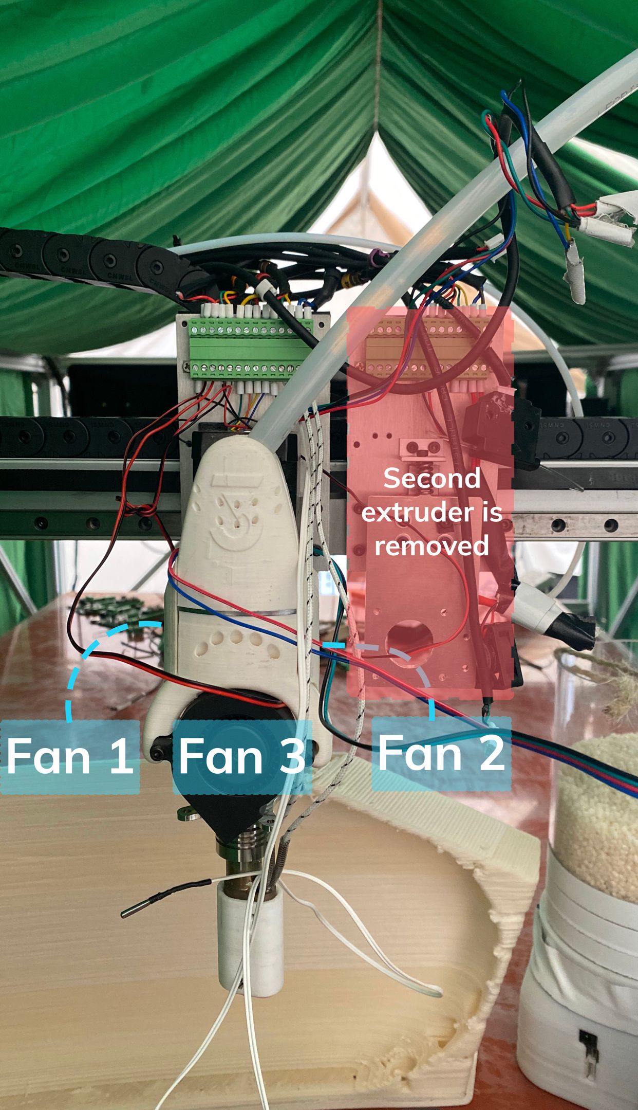
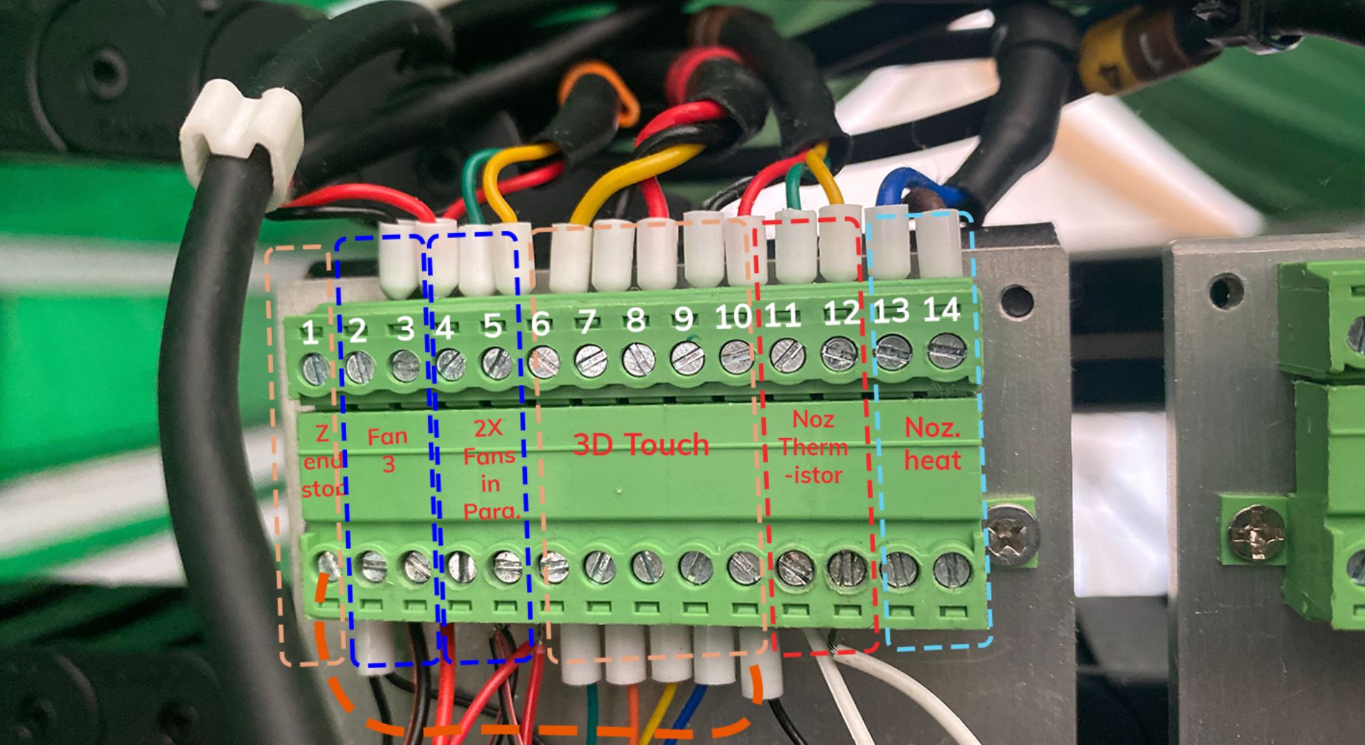
I test for continuity with Ohms on my RadioShack Multimeter and get 140 accross two wires on thermistor disconnected and connected To points 11-12. The same reading when board is on or off. I had some readings accross the noz thermistor and noz heat cartridge terminals (testing accross points 11 and 13) when the heating cartridge was disconnected but when I connected the heat cartridge it stopped. Nothing at all. I think there is a damaged wire somewhere. I am testing and will let you know results.
Not sure what you mean about the thermocouple but I keep going as you instruct. My thanks
-
@charles-fraser ok for the thermocouple there is an issue with the name when used on an expansion board. For now please change the line in config.g to
M308 S0 P"1.spi.cs0" Y"thermocouplemax31856"Note I have removed the "-"
then run
M98 P"0:/sys/config.g"
and hopefully we will be back to no errors.
(and maybe even a reading for bed temperature)
I hope you find the source of the wiring issue. As a point of reference I would expect the thermistor to have a reading in the vicinity of 10K or 100K at room temperature (they come in many different types so it might be different).
-
Thanks Tony I will try that just now. I have just had a long chat with Juan the inventor of opensource Lily Pellet Extruder Website that I have hooked up here printing pellets from a 3mm nozzle and about 500-1000g / hour and costing only 500-1000$ for the extruder. Juan's manufacture partner in Spain has just said he can't fulfill the orders c. 20 orders Juan has for extruders because he is too busy with other stuff so Juan is stuffed and looking for a new manufacture partners. He has some amazing designs for a V2 extruder and a colour system that mixes RMCYB in a liquid master batch into the heated chamber to create colour prints or feed additives like fire resistant chemicals into the liquid masterbatch. Pellets reduce cost of printing 10 x and using a shredder you can shred old prints and certain household waste to create materials for the extruder. It's the whole idea behind the system. We will be at the Additt conference in Bilbao and wonder if you will be there and if you know anyone who might want to process the c. $20k worth of orders for the extruder that can be simply 3D printed for the high temp plastic parts and CNC milled for the auger and hopper? Orders that are on the table now. Perhaps this is something the opensource community here might want to discuss, but he's looking for partners to take the product forwards so I'm going to try and help him find what he needs thereby.

I'll send the results from the updated config just now. Thanks
Charles