Geometry / Machine movement question
-
This has taken me a few stabs over the years to ensure I have a full comprehension of how the machines under Duet control actually move at a low level. If this has already been further explained since the last time I asked please share links.
The following questions are to help me understand how the dues will command the movement of a simple Cartesian system. The questions relate to the motion of single axis, and assume the motion of that axis won't be limited by another.
'Feed rate' in my assumptions/questions refers to what is being commanded of the axis, not what is directly set in the g-code. The feed rate set in the g-code may remain constant while the feed rate required of a specific axis will be dependant on the angle of the move relative to the axis.
Are the following assumptions correct?
[Following ignores instant speed...]
- The feed rate is a target value which will not be exceeded for the duration of the move.
- If the feed rate is higher for the subsequent move, the feed rate will remain as set for the current vector until the current move is complete. All acceleration will occur in the subsequent vector.
- If the feed rate for the subsequent move is lower than the current move a deceleration will occur at the end of the current vector. The feed rate at the end of the current vector will equal the feed rate for the subsequent vector.
- The final velocity for current move will be 0 if there is a change of direction between current move and the subsequent move.
The following questions apply to a single axis and relate to how instant speed is applied. In these questions acceleration may be negative:
- If the change in feed rate between two moves is greater than the instant speed setting is the axis commanded to instantly change speed by the instant speed value, then continue to accelerate for the required change in feed rate?
- Is instant speed only applied where the difference in feed rate from one move to the next is not greater than the instant speed setting regardless of the initial velocity?
- Is instant speed only applied when both the current and subsequent move feed rates are lower than the instant speed setting?
- Is instant speed only applied to moves starting from an initial velocity of zero?
- If there is a change in direction for the axis and the feed rate in the opposite direction for the subsequent move is less than the instant speed setting can the remainder of the instant speed be used at the end of the current move? In other words does the axis decelerate to the remainder of the instant speed value at the end of the current move instead of zero and then instantly accelerate up to the target feed rate for the subsequent move at the start of the subsequent move?
-
Ok, taking testing into my own hands! I've got a test script that creates a regular polygon of a set radius and repeats that until the estimated build time is half an hour. The build file is stripped down and forces specific acceleration, instant speed, and max speed settings at the end of the file it calls m98 p"config.g" as a safety.
Rookie mistake with the first set of files, I set radius to 50mm meaning the build time is dominated constant speed printing rather than jerk/acceleration, etc. I'll re-prep my files for 5mm radius and try again after my coffee!
-
This test script is just running x and y axes at the moment and lapping over the same points without moving the z axis.
I expect there to be a critical number of sides before instant speed comes into play.
If however the instant speed is different for the first and last part of a block of print commands then that will come out of the wash when I print a grid of these parts with extrusion commands too.
Start simple, get my model to match results from the duet simulation then increase complexity.
Edit: modding code for fixed side length, rather than radius!
-
@doctrucker Hi Wes. Not sure that I fully understand your questions but this might help. https://duet3d.dozuki.com/Wiki/Gcode#Section_G0_G1_Move
Specifically this bit - quote.............
"Feedrate
G1 F1500
G1 X50 Y25.3 E22.4In the above example, we set the feedrate to 1500mm/minute on line 1, then move to 50mm on the X axis and 25.3mm on the Y axis while extruding 22.4mm of filament between the two points.
G1 F1500
G1 X50 Y25.3 E22.4 F3000However, in the above example, we set a feedrate of 1500mm/minute on line 1, then do the move described above accelerating to a feedrate of 3000 mm/minute as it does so. The extrusion will accelerate along with the X and Y movement, so everything stays synchronized."
............. end of quote
And this bit - quote............
"Feedrate is treated as simply another variable (like X, Y, Z, and E) to be linearly interpolated. This gives complete control over the acceleration and deceleration of the printer head in such a way that ensures that everything moves smoothly together, and the right volume of material is extruded at all points. The feedrate specified may not be reached due to a lower feedrate limit being configured, or the move being too short for the axis to accelerate and decelerate in time.
"
...... end of quote.Does that help?
-
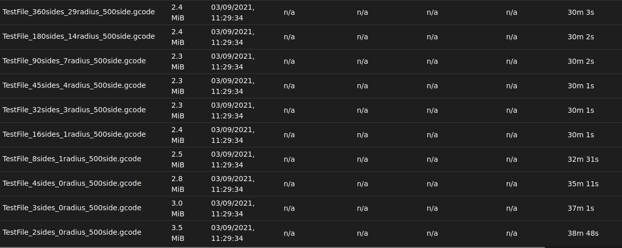
There's the good simulation time drop that I needed! 0.5mm side length regular polys, X&Y move only and repeated until total distance / feed rate predicts a 30 min build time. So for all aside from the first 4 builds there is likely negligible acceleration and all change of direction is instant speed changes.
-
@deckingman Some interesting points there and I had thought (perhaps in error) @dc42 had said the following two would behave exactly the same...
G1 F1200
G1 X34 Y23 F2400G1 F2400
G1 X34 Y23All helps figure the system out. I want to be able to model what the duet will do for a specific build file. Once my simulation time matches the print time (at least for simple cases) I will be content!
-
@deckingman said in Geometry / Machine movement question:
@doctrucker Hi Wes. Not sure that I fully understand your questions but this might help. https://duet3d.dozuki.com/Wiki/Gcode#Section_G0_G1_Move
Specifically this bit - quote.............
"Feedrate
G1 F1500
G1 X50 Y25.3 E22.4In the above example, we set the feedrate to 1500mm/minute on line 1, then move to 50mm on the X axis and 25.3mm on the Y axis while extruding 22.4mm of filament between the two points.
G1 F1500
G1 X50 Y25.3 E22.4 F3000However, in the above example, we set a feedrate of 1500mm/minute on line 1, then do the move described above accelerating to a feedrate of 3000 mm/minute as it does so. The extrusion will accelerate along with the X and Y movement, so everything stays synchronized."
............. end of quote
And this bit - quote............
"Feedrate is treated as simply another variable (like X, Y, Z, and E) to be linearly interpolated. This gives complete control over the acceleration and deceleration of the printer head in such a way that ensures that everything moves smoothly together, and the right volume of material is extruded at all points. The feedrate specified may not be reached due to a lower feedrate limit being configured, or the move being too short for the axis to accelerate and decelerate in time.
"
...... end of quote.Does that help?
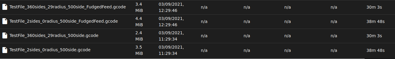
Unless I have misunderstood I can confirm that is either incorrect, or the simulation is incorrect. I just tested with the 360 and 2 sides and got the same result.
Snippet from the 360 side 'fudged' file:
; Start Header.

M350 X16 Y16 Z16 A16 E16 B16 I1 ; Microstepping
M92 X400 Y400 Z400  A41.667 E1600 B1600; Steps per mm
M566 X500 Y500 Z500  A6000 E1000 B1000; Max instant speed (mm/min or deg/mm)
M203 X2500 Y2500 Z2500  A120000 E1000 B1000; Max speed (mm/min or deg/mm)
M201 X150 Y150 Z150  A120000 E3000 B3000; Acceleration (mm/s^2 or deg/s^2)

M200 D13                           ; Set filament diameter.
M207 S0 R0 F3600 T3600 Z2.0        ; Set retract and z-hop for G10/G11.
G21                                ; Set units to millimeters.
G90                                ; Use absolute coordinates.
M83                                ; Use relative distances for extrusion.

;G11                                ; Unretract.

; End Header.
; Start gcode body.
G1 F1200 ;  Set feedrate.
; Start lap 0.
G1 F600
 G1 X28.64716 Y-0.25000 F1200; Point 0
G1 F600
 G1 X28.64716 Y0.25000 F1200; Point 1
G1 F600
 G1 X28.63844 Y0.74992 F1200; Point 2
G1 F600
 G1 X28.62099 Y1.24962 F1200; Point 3
G1 F600
Snippet from my original 360 side file:
; Start Header.

M350 X16 Y16 Z16 A16 E16 B16 I1 ; Microstepping
M92 X400 Y400 Z400  A41.667 E1600 B1600; Steps per mm
M566 X500 Y500 Z500  A6000 E1000 B1000; Max instant speed (mm/min or deg/mm)
M203 X2500 Y2500 Z2500  A120000 E1000 B1000; Max speed (mm/min or deg/mm)
M201 X150 Y150 Z150  A120000 E3000 B3000; Acceleration (mm/s^2 or deg/s^2)

M200 D13                           ; Set filament diameter.
M207 S0 R0 F3600 T3600 Z2.0        ; Set retract and z-hop for G10/G11.
G21                                ; Set units to millimeters.
G90                                ; Use absolute coordinates.
M83                                ; Use relative distances for extrusion.

;G11                                ; Unretract.

; End Header.
; Start gcode body.
G1 F1200 ;  Set feedrate.
; Start lap 0.
G1 X28.64716 Y-0.25000 ; Point 0
G1 X28.64716 Y0.25000 ; Point 1
G1 X28.63844 Y0.74992 ; Point 2
G1 X28.62099 Y1.24962 ; Point 3
Result:
-
Interesting aside while working through the build time estimator.
Since the axes may not need to stop at the end of a vector and the each vector length may be a fraction of the total time required to accelerate up to, or down from the target feed rate the look ahead is a necessity. Currently my software is reading in blocks of either continuous print free movement, or continuous printing movement. With the build time estimator I will have to adapt that to a flexible look-ahead where it reads in enough of the following moves to ensure the system can stop when it needs to.
This will take a little further programming!