Connecting RGBW 24V LED strip to Duet 2 WIFi board
-
I tried added '^' to all four heater pins and nothing changed.
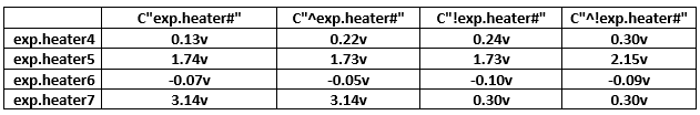
I decided to test my board by enabling the pull up resistor '^' and inverting the input '!' to see how it affects the voltage. The results I got are shown below, as you can see the voltages are all over the place.
I also tried added MT3608 DC boosters to the pins in hope that that might boost the voltage to 3.3v but every time I connect it, the voltage coming from the pins just drops.
-
@csosa
That's confusing...are you sure about the GND pin you measured voltages against? Try using #pin2 from the expansion header.
Did you try to run M98 P"config.g" to see if any errors pop up?Maybe there's an issue with using a heater output without defining a temp-sensor?
Anyone who can chime in here? -
@o_lampe said in Connecting RGBW 24V LED strip to Duet 2 WIFi board:
Maybe there's an issue with using a heater output without defining a temp-sensor?
Something like
M950 H4 C"nil" ; undefine heater4 pin M950 P4 C"exp.heater4" Q250 -
I ran the M98 P"config.g" and got back the following
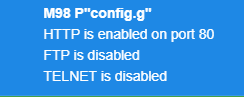
I am not sure is FTP and TELNET are suppose to be enabled but other than that it doesn't look like there are any errors in config.g
I also switched the GND to pin 2 (which is normally connected to my BL Touch). I checked the voltage from all four wires and got the following.
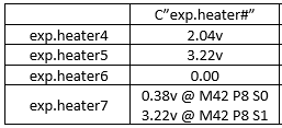
As you can see the voltage is all over the place expect for exp.heater7 which is working as it should. For heater pins 4 ,5 and 6 the voltage didn't change when I ran M42 P# S1.
While I was testing the last two wires (going to exp.heater6 and exp.heater7) my cooling fan started to turn on, the WIFI would disconnect and the diag. light would briefly flash. It did this a few time randomly so I unplugged all the wires going to the expansion pins. Now every time I turn it on it connects to WIFI but after a few minutes it disconnects and the diag. LED starts flashing.
Looks like I might have to erase the firmware and reinstall it before being able to test the "nil" function to undefine the heater pins.
-
@csosa
Maybe the fan went on, because you've used the same P# in a fan declaration?
I've tested all 5 heaters without "nil", mentioning that was just a last straw. In my case, they were real heaters, which can make a difference. -
@csosa
From the Wiki:M42 switches a general purpose I/O pin. Use M42 Px Sy to set pin x to value y. The S field may be in the range 0..1 or 0..255.How does M42 know that S1 isn't meant as 1 of 255 ?
Answer: use S1.0 to tell it to switch on 100% -
Since my board kept disconnecting from the wifi and the diag light start flashing. I erased the firmware and tried reinstall it again using Fallback procedure #2. I am not sure why but the firmware doesn't seem to install on the board, the diag light wont turn off. I'm using Bossa to write and verify the firmware, but afterwards the diag light wont turn off. Usually I'm able to just erase the board and reinstall the firmware using Bossa and later YAT to setup the WIFI and make updates but this time it doesn't look like Bossa is installing anything. I also tried installing the firmware using SAM-BA version 2.17 but it wouldn't connect either.
-
@csosa
A last straw is to remove all wires, steppers, probes from the board and try Bossa again, but I'm afraid your controller is partially dead.
It's probably time to put a new Duet board on your x-mas wishlist? -
Sadly I think you are right

I did some research and I am thinking of ordering the Duet 3 mini 5+. Since it has a connector for the LED, hopefully it will be easier to set up.
However according to duet guide the LEDs have to be NeoPixel in order to work. Do you think it is possible to get away with using another led strip that used the same WS2812 LED used by NeoPixel. I'm asking because BTF-LIGHTING have basically the same set up but are cheaper.
-
@csosa
I'm afraid the NeoPixel LED strip comes with a special interface,You'd still need 4 GPIO pins and the external driver board.
The BTF strip uses the same it seems (but not tested)BTW: It's probably not a good time to buy LED strips....better wait until X-mas is over
")
-
You're probably right, but I want to finish this project as soon as possible lol. Thanks you for all your help, I will let you know if I can get the BTF-Lighting LEDs to work.