tool change - y slide?!?!
-
hey community
I have the problem, that y is moving in + direction in regularly moves.
That only happens when changing tools while printing. BUT NOT when changing tools just (when nothing is printed) --> I changed more than 100 times when not printing. Everything fine....A few weeks ago, I have been printing with tool change for weeks without problems.
With printing after a few layers the coupler has moved so far Y+ (see picuture) that the TC doesn´t fit anymore to collect a new tool. See picture.
I already tried_
- different cura version
- update duet 3 and boards
- it´s definetly not a physical problem
Is there somebody who has/had the same problem?
---very happy for any suggestionens.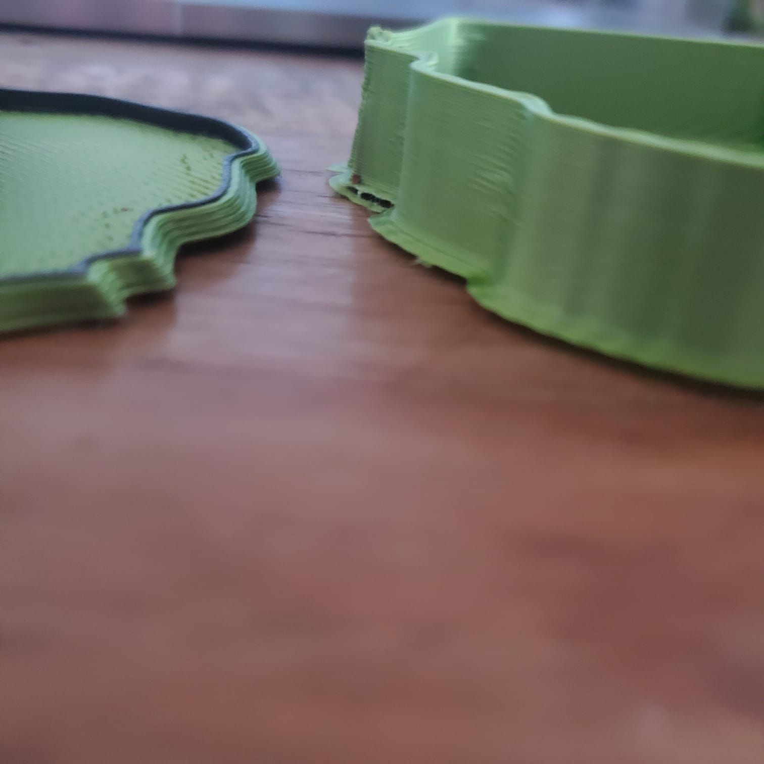
Duet 3 Send code... Status Idle Mode: FFF Tool Position X 68.5 Y 10.0 Z 50.90 C 200.0 Extruder Drives Drive 0 186.0 Drive 1 895.1 Drive 2 0.0 Speeds Requested Speed 0 mm/s Top Speed 0 mm/s Sensors Vin 24.0 V V12 12.2 V MCU Temperature 41.6 °C Z-Probe 0 Tools Extra Control Heaters Tool Heater Current Active Standby Tool 0 T0 - Load Filament Heater 1 off 27.0 °C 0 0 Tool 1 T1 - Load Filament Heater 2 standby 209.0 °C 209 209 Tool 2 T2 - Load Filament n/a n/a 0 0 Bed Heater 0 active 62.9 °C 63 0 Temperature Chart System Directory 0:/sys/config.g ; Configuration file for Duet 3 (firmware version 3) ; executed by the firmware on start-up ; ; generated by RepRapFirmware Configuration Tool v3.2.3 on Mon Aug 02 2021 16:15:35 GMT+0200 (Mitteleuropäische Sommerzeit) ; General preferences G90 ; send absolute coordinates... M83 ; ...but relative extruder moves M550 P"Duet 3" ; set printer name M552 S1 P192.168.2.108 ; Wifi G4 S4 M574 C1 S3 M574 C0 Z0 ; No C Z endstop M915 P1.2 C S0 F0 R1 ; Drives M569 P0.0 S1 ; physical drive 0.0 goes forwards M569 P0.1 S1 ; physical drive 0.1 goes forwards M569 P0.2 S0 ; physical drive 0.2 goes forwards M569 P0.3 S0 ; physical drive 0.2 goes forwards M569 P0.4 S0 ; physical drive 0.2 goes forwards M569 P0.5 S0 ; physical drive 0.2 goes forwards M569 P1.0 S0 ; physical drive 0.2 goes forwards M569 P1.2 S0 ; physical drive 0.2 goes forwards M569 P20.0 S0 ; physical drive 121.0 goes forwards M569 P21.0 S1 ; physical drive 122.0 goes forwards M569 P123.0 S1 ; physical drive 123.0 goes forwards M584 X1.0 Y0.0:0.1 Z0.2:0.3:0.4:0.5 C1.2 E20.0:21.0:123.0 ; set drive mapping M350 X128 Y128 Z128 E16:16:16 I1 ; configure microstepping with interpolation M92 X1280.00 Y1280.00 Z5120.00 C91.022 E409.00:409.00:409.00 ; set steps per mm M566 X1800.00 Y1800.00 Z30.00 C3000 E3.00:3.00:3.00 ; set maximum instantaneous speed changes (mm/min) M203 X15000.00 Y15000.00 Z800.00 C5000 E6000.00:6000.00:6000.00 ; set maximum speeds (mm/min) M201 X2000.00 Y2000.00 Z500.00 C400 E2500.00:2500.00:2500.00 ; set accelerations (mm/s^2) M906 X1300 Y1300 Z2300 C400 E1000:1000:1000 I30 ; set motor currents (mA) and motor idle factor in per cent M84 S30 ; Set idle timeout M671 X-80:-80:930:930 Y-80:930:930:-80 S20 ; leadscrews at front left1 and n´back2. back rigth3 and front4 ; Axis Limits M208 X-10 Y-89.4 Z0 S1 ; set axis minima M208 X860 Y890 Z850 S0 ; set axis maxima ; Endstops M574 X2 S1 P"^io3.in" ; configure active-high endstop for high end on X via pin ^io3.in M574 Y2 S1 P"^io1.in" ; configure active-high endstop for high end on Y via pin ^io1.in ; Z probe M558 P5 C"io2.in" H8 F2000 I0 T5000 ; Set Z probe type to switch, the axes for which it is used and the dive height + speeds G31 P200 X5 Y30 Z0 ; Set Z probe trigger value, offset and trigger height; Z probe M556 S50 X0 Y0 Z0 ; set orthogonal axis compensation parameters M557 X50:800 Y50:800 S37.5 ; define mesh grid ; Heaters M308 S0 P"temp0" Y"thermistor" T100000 B4138 ; configure sensor 0 as thermistor on pin temp0 M950 H0 C"out0" T0 ; create bed heater output on out0 and map it to sensor 0 M307 H0 B0 R0.243 C586.2 D33.87 S1.00 V0 ; disable bang-bang mode for the bed heater and set PWM limit M140 H0 ; map heated bed to heater 0 M143 H0 S120 ; set temperature limit for heater 0 to 120C M308 S1 P"20.temp0" Y"thermistor" T100000 B4138 ; configure sensor 1 as PT1000 on pin 121.temp0 M950 H1 C"out2" T1 ; create nozzle heater output on out1 and map it to sensor 1 M307 H1 B0 R1.553 C487.8 D10.35 S1.00 V0 ; disable bang-bang mode for heater and set PWM limit M143 H1 S250 ; set temperature limit for heater 1 to 250C M308 S2 P"21.temp0" Y"thermistor" T100000 B4138 ; configure sensor 2 as PT1000 on pin 122.temp0 M950 H2 C"out1" T2 ; create nozzle heater output on 122.out0 and map it to sensor 2 M307 H2 B0 B0 R1.553 C487.8 D10.35 S1.00 V0 ; disable bang-bang mode for heater and set PWM limit M143 H2 S250 ; set temperature limit for heater 2 to 250C M308 S3 P"123.temp0" Y"pt1000" R2200 ; configure sensor 3 as PT1000 on pin 123.temp0 M950 H3 C"123.out0" T3 ; create nozzle heater output on 123.out0 and map it to sensor 3 M307 H3 B0 S1.00 ; disable bang-bang mode for heater and set PWM limit M143 H3 S250 ; set temperature limit for heater 3 to 250C ; Fans M950 F0 C"20.out1" Q500 ; create fan 0 on pin 121.out1 and set its frequency M106 P0 S0 H-1 ; set fan 0 value. Thermostatic control is turned off M563 P0 D0 H1 ; tool uses extruder 0, heater 1 M950 F1 C"20.out2" Q500 ; create fan 1 on pin 121.out2 and set its frequency M106 P1 S1 H1 T45 ; set fan 1 value. Thermostatic control is turned on M563 P0 D0 H1 F1 ; tool uses extruder 0, heater 1 M950 F2 C"21.out1" Q500 ; create fan 2 on pin 122.out1 and set its frequency M106 P2 S1 H-1 ; set fan 2 value. Thermostatic control is turned off M950 F3 C"21.out2" Q500 ; create fan 3 on pin 122.out2 and set its frequency M106 P3 S1 H2 T45 ; set fan 3 value. Thermostatic control is turned on M950 F4 C"123.out1" Q500 ; create fan 4 on pin 123.out1 and set its frequency M106 P4 S1 H-1 ; set fan 4 value. Thermostatic control is turned off M950 F5 C"123.out2" Q500 ; create fan 5 on pin 123.out2 and set its frequency M106 P5 S1 H3 T45 ; set fan 5 value. Thermostatic control is turned on M950 F6 C"out4" Q500 ; create fan 6 on pin out4 and set its frequency M106 P6 S1 H-1 ; set fan 6 value. Thermostatic control is turned off M950 F7 C"out5" Q500 ; create fan 7 on pin out5 and set its frequency M106 P7 S1 H T45 ; set fan 7 value. Thermostatic control is turned on M950 F8 C"out8" Q500 CMagnet0 ; create magnet 0 on pin out9 and set its frequency M106 P0 S0 H-1 ; set fan 0 value. Thermostatic control is turned off M950 F9 C"out9" Q500 CMagnet1 ; create magnet 0 on pin out9 and set its frequency M106 P0 S0 H-1 ; set fan 0 value. Thermostatic control is turned off M950 F10 C"1.out6" Q500 CMagnet2 ; create magnet 0 on pin out9 and set its frequency M106 P0 S0 H-1 ; set fan 0 value. Thermostatic control is turned off M950 F11 C"out7" Q500 CMagnet3 ; create magnet 0 on pin out9 and set its frequency M106 P0 S0 H-1 ; set fan 0 value. Thermostatic control is turned off ; Tools M563 P0 D0 H1 F0 ; define tool 0 G10 P0 X-29.8 Y-28.65 Z-39.65 ; set tool 0 axis offsets G10 P0 R0 S0 ; set initial tool 0 active and standby temperatures to 0C M563 P1 D1 H2 F2 ; define tool 1 G10 P1 X-29 Y-28.45 Z-40 ; set tool 1 axis offsets G10 P1 R0 S0 ; set initial tool 1 active and standby temperatures to 0C M563 P2 D2 H3 F4 ; define tool 2 G10 P2 X0 Y0 Z0 ; set tool 2 axis offsets G10 P2 R0 S0 ; set initial tool 2 active and standby temperatures to 0C ; Custom settings are not defined ; Miscellaneous M911 S10 R11 P"M913 X0 Y0 G91 M83 G1 Z3 E-5 F1000" ; set voltage thresholds and actions to run on power loss -
@gruna-studio please post the bit of gcode in a print that recreates this
-
I can only upload 4mb to the forum. the file has 10mb....

-
@gruna-studio it looked like it happened at a particular point in the file, can you cut down the file to just after the issue occurred (worked out from the Z height or layer)
-
@t3p3tony I am working with gruna-studio to investigate the issue. To test some stuff I made a short script that does about 10 changes back and forth with some moves inbetween. This was confirmed to cause the issue as well.
MoveTC10_test.gcodeTo furter elaborate on the issue. Toolchanges seem to cause a growing y-offset, eventually leading to the toolchanger failing to pickup a tool and leaning prints. IIRC, a re-home of the axis resolves the issue. Also manually changing tools (selecting in DWC) many times does not seem to reproduce the issue.
-
@nxt-1 @gruna-studio
Thanks for the file, I have looked at the file and it appears to include bits of tpostN.g files which is a bit confusing, are those just comments left over from some other testing or something else?
Also I see a G1 D1 and G1 D0 commands what are the "D"s aiming to do?
Please can you upload your tool change macros for tool 0 and tool 1 for reference.
-
@t3p3tony I noticed the D's as well and the fact that that parameter is not documented on the wiki. The reason I left it in there is because I copied/modified a g-code script (created by cura) I got from OP. I believe they are silently ignored by the Duet.
After some more testing we can confirm that just tool changes work. MoveTC10_test_2.gcode contains basically only toolchanges and that was reported working without issue.
So I figured somewhere between script 2 and script 1 lies an issue in the g-code commands.
My next step was to slowly remove more and more gcode starting from script 1 and see at what point it started working.
MoveTC10_test_3.gcode -> not working
MoveTC10_test_4.gcode -> not working
MoveTC10_test_5.gcode -> not working
MoveTC10_test_6.gcode -> reported not working but slower. Only after 1,5 runs of the script did the offset become to large for a tool change to fail. (normally failure is reported after ~8 changes)EDIT: At this point I don't really know how to advice/test anyfurter. Since we can almost certainly rule out mechanical issues, since script 2 works without issue. But anything more that just tool changes does give issue ¯_(ツ)_/¯
Here are the free/pre scripts for T0, they are identical for T1
; tfree0.g
; called when tool 0 is freed

;Drop the bed
G91
G1 Z4 F1000
G90

;Purge nozzle
;M98 P"purge.g"

;Move In
G53 G1 X282 Y10 F10000

;Magnet 100 prozent
M106 P10 S1
M106 P11 S1

;brush cooler
M106 P0 S1

;touch
G53 G1 X282.1 Y-86.4

;Open Coupler
M98 P"/macros/Coupler - Unlock"

;fan off
M106 P2 S1

;Move Out
G53 G1 X282 Y10 F7000

;magnet 50 prozent
M106 P10 S0.5
M106 P11 S0.5
; tpre0.g ; called before tool 0 is selected ;Unlock Coupler M98 P"/macros/Coupler - Unlock" ;brush cooler M106 P0 S0 ;Move in G1 X282.1 Y10 F10000 ;Collect G1 X282.1 Y-86.7 F4000 ;Close Coupler M98 P"/macros/Coupler - Lock" ;Magnet 0 prozent M106 P10 S0 M106 P11 S0 ;WARNING! WARNING! WARNING! WARNING! WARNING! WARNING! WARNING! WARNING! WARNING! WARNING! WARNING! WARNING! ;if you are using non-standard length hotends ensure the bed is lowered enough BEFORE undocking the tool! G91 G1 Z0 F400 G90 ;Move Out G1 X282.1 Y-35 F7000ps I have no idea why the formum gives them different styling.