1HCL Closed Loop - layer shifts - Timing?
-
Heey , Since I´ve been installing the 1HCL´s I have to fight with layer shifts. After PID Tuning (what is not really possible for my 2 Y Motors) I have just bigger but less ofter layer shifts.
I think it´s an combination of Timing and PID Tuning. The PID Tuning infected the count of shifts , but the biggest step to have just less often shifts, was the Timing. Where I have strange numbers now. With the custom settings I had a lot of shifts.
I use the suggested nema 17 stepper of steperonline which is in the docu.
When the Y axis shifts, both motors made the same wrong move.
I´ve been printing almost 2 kg of filament and I´m not sure what I should describe you more then that was I´ve written. I would be very happy about precision question or helpful suggestions.
Thanks to all
Richard@T3P3Tony
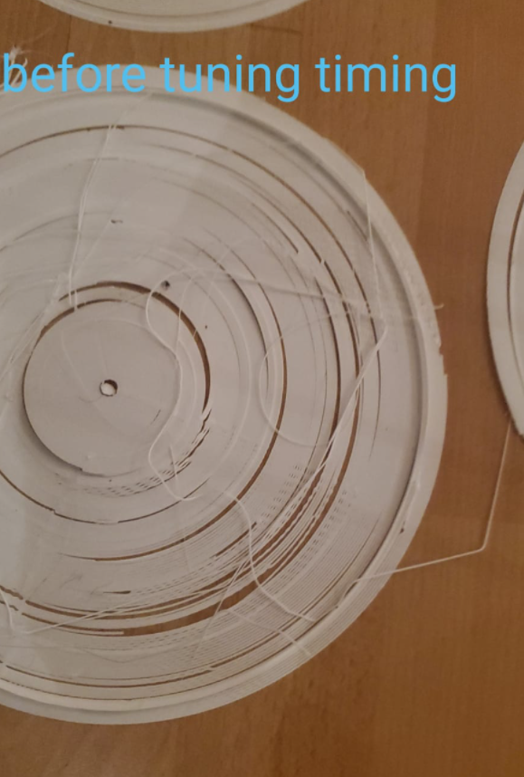
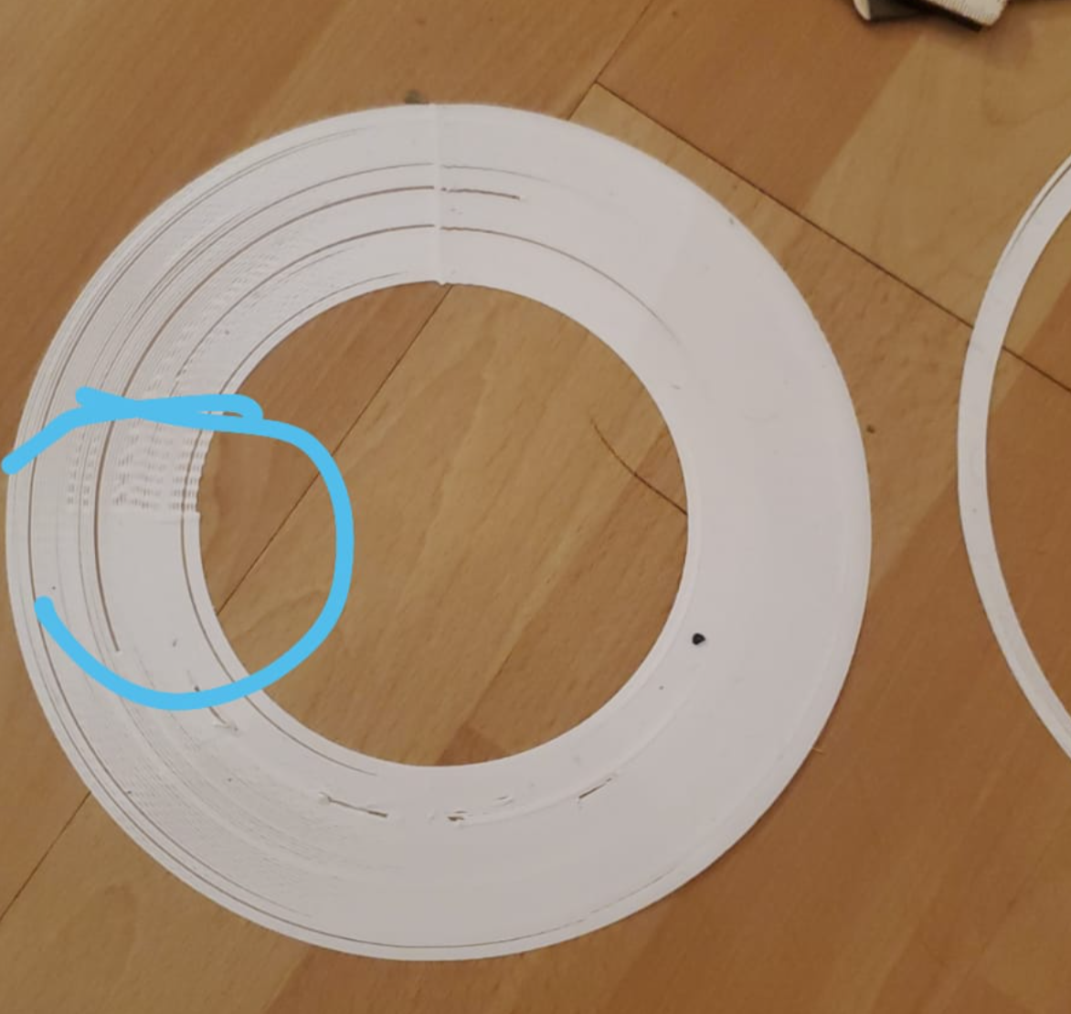
Picture 1 before Timing and PID tuning
Pic 2
G code and all settings right now. After Tuning PID and Timing settings.
; Configuration file for Duet 3 (firmware version 3) ; executed by the firmware on start-up ; ; generated by RepRapFirmware Configuration Tool v3.2.3 on Mon Aug 02 2021 16:15:35 GMT+0200 (Mitteleuropäische Sommerzeit) ; General preferences G90 ; send absolute coordinates... M83 ; ...but relative extruder moves M550 P"Duet 3" ; set printer name M552 s1 M587 S"AndroidAPebc3_EXT" P"hhhhhhhh" G4 S4 M574 C1 S3 M574 C0 Z0 M915 P0.5 C S0 F0 R1 ; Drives ;closed loop M569.1 P20.0 T2 C5 R69 I0 D0.06 H10 ; Configure the 1HCL board at CAN address.20quadrature encoder 128 steps/motor full M569.1 P21.0 T2 C5 R69 I0 D0.06 H10 ; Configure the 1HCL board at CAN address.21quadrature encoder 128 steps/motor full step. M569.1 P22.0 T2 C5 R69 I0 D0.06 H10 ; Configure the 1HCL board at CAN address.21quadrature encoder 128 steps/motor full step. M569 P20.0 D4 S1 T60:60:80:80 ; Configure the motor on the 1HCL at can address 20 as being in closed-loop drive mode (D4) and not reversed (S1) M569 P21.0 D4 S0 T60:60:80:80 ; Configure the motor on the 1HCL at can address 21 as being in closed-loop drive mode (D4) and not reversed (S1) M569 P22.0 D4 S1 T60:60:80:80 ; Configure the motor on the 1HCL at can address 21 as being in closed-loop drive mode (D4) and not reversed (S1) Other drives; open loop; M569 P0.0 S1 ; physical drive 0.0 goes forwards M569 P0.1 S1 ; physical drive 0.2 goes forwards M569 P0.2 S1 ; physical drive 0.2 goes forwards M569 P0.3 S1 M569 P0.5 S0 M569 P100.0 S0 ; physical drive 0.2 goes forwards M584 X22.0 Y20.0:21.0 Z0.0:0.1:0.2:0.3 C0.5 E100.0 ; set drive mapping M350 X1 Y1 Z128 E16:16:16 I1 ; configure microstepping with interpolation M92 X100.00 Y100.00 Z5120.00 C91.022 E409.00:409.00:409.00 ; set steps per mm M566 X600.00 Y600.00 Z60.00 C3000 E600.00:600.00:600.00 ; set maximum instantaneous speed changes (mm/min) M203 X8000.00 Y8000.00 Z500.00 C10000 E6000.00:6000.00:6000.00 ; set maximum speeds (mm/min) M201 X1600.00 Y1600.00 Z500.00 C400 E2500.00:2500.00:2500.00 ; set accelerations (mm/s^2) M906 X1700 Y1700:1700 Z2300:2300:2300:2300 C400 E1000 I30 ; set motor currents (mA) and motor idle factor in per cent M84 S300 ; Set idle timeout M671 X-110:-110:1140:1140 Y-100:1140:1140:-110 S20 ; leadscrews at front left1 and n´back2. back rigth3 and front4 ; Axis Limits M208 X-10 Y0 Z0 S1 ; set axis minima M208 X1000 Y890 Z850 S0 ; set axis maxima ; Endstops M574 X2 S1 P"^22.io1.in" ; configure active-high endstop for high end on X via pin ^io3.in M574 Y2 S1 P"^20.io1.in+21.io1.in" ; configure active-high endstop for high end on Y via pin ^io1.in ; Z probe M558 P5 C"0.io1.in" H8 F2000 I0 T5000 ; Set Z probe type to switch, the axes for which it is used and the dive height + speeds G31 P200 X5 Y30 Z0 ; Set Z probe trigger value, offset and trigger height; Z probe M556 S50 X0 Y0 Z0 ; set orthogonal axis compensation parameters M557 X50:800 Y50:800 S37.5 ; define mesh grid ; Heaters M308 S1 P"100.temp0" Y"thermistor" T100000 B4138 ; configure sensor 1 as PT1000 on pin 121.temp0 M950 H1 C"100.out0" T1 ; create nozzle heater output on out1 and map it to sensor 1 M307 H1 B0 R1.553 C487.8 D10.35 S1.00 V0 ; disable bang-bang mode for heater and set PWM limit M143 H1 S250 ; set temperature limit for heater 1 to 250C M308 S0 P"temp0" Y"thermistor" T100000 B4138 ; configure sensor 0 as thermistor on pin temp0 M950 H0 C"out0" T0 ; create bed heater output on out0 and map it to sensor 0 M307 H0 B0 R0.243 C586.2 D33.87 S1.00 V0 ; disable bang-bang mode for the bed heater and set PWM limit M140 H0 M143 H0 S120 ; Fans M950 F0 C"100.out1" Q500 ; create fan 0 on pin 121.out1 and set its frequency M106 P0 S0 H-1 ; set fan 0 value. Thermostatic control is turned off M563 P0 D0 H1 ; tool uses extruder 0, heater 1 M950 F1 C"100.out2" Q500 ; create fan 1 on pin 121.out2 and set its frequency M106 P1 S1 H1 T45 ; set fan 1 value. Thermostatic control is turned on M563 P0 D0 H1 F1 ; tool uses extruder 0, heater 1 M950 F2 C"3.out1" Q500 ; create fan 2 on pin 122.out1 and set its frequency M106 P2 S1 H-1 ; set fan 2 value. Thermostatic control is turned off M950 F3 C"3.out2" Q500 ; create fan 3 on pin 122.out2 and set its frequency M106 P3 S1 H2 T45 ; set fan 3 value. Thermostatic control is turned on M950 F4 C"out1" Q500 ; create fan 4 on pin 123.out1 and set its frequency M106 P4 S1 H-1 ; set fan 4 value. Thermostatic control is turned off M950 F5 C".out2" Q500 ; create fan 5 on pin 123.out2 and set its frequency M106 P5 S1 H3 ; set fan 5 value. Thermostatic control is turned on M950 F6 C"2.out6" Q500 ; create fan 6 on pin out4 and set its frequency M106 P6 S0 H-1 ; set fan 6 value. Thermostatic control is turned off M950 F7 C"2.out7" Q500 ; create fan 7 on pin out5 and set its frequency M106 P7 S0 H ; set fan 7 value. Thermostatic control is turned on M950 F8 C"2.out8" Q500 CMagnet0 ; create magnet 0 on pin out9 and set its frequency M106 P0 S0 H-1 ; set fan 0 value. Thermostatic control is turned off M950 F9 C"1.out6" Q500 CMagnet1 ; create magnet 0 on pin out9 and set its frequency M106 P0 S0 H-1 ; set fan 0 value. Thermostatic control is turned off M950 F10 C"1.out6" Q500 CMagnet2 ; create magnet 0 on pin out9 and set its frequency M106 P0 S0 H-1 ; set fan 0 value. Thermostatic control is turned off M950 F11 C"out7" Q500 CMagnet3 ; create magnet 0 on pin out9 and set its frequency M106 P0 S0 H-1 ; set fan 0 value. Thermostatic control is turned off ; Tools M563 P0 D0 H1 F0 ; define tool 0 G10 P0 R0 S0 ; set initial tool 0 active and standby temperatures to 0C ; Custom settings are not defined ; Miscellaneous M911 S10 R11 P"M913 X0 Y0 G91 M83 G1 Z3 E-5 F1000" ; set voltage thresholds and actions to run on power loss -
@gruna-studio which firmware are you using? Please use 3.4.0rc2. Note, the ranges of PID constants have changed since firmware 3.3 and early 3.4 beta versions, so you will need to re-establish what values work on your machine..
Duet WiFi hardware designer and firmware engineer
Please do not ask me for Duet support via PM or email, use the forum
http://www.escher3d.com, https://miscsolutions.wordpress.com -
@dc42
I've been tuning etc everything with 3.4rc1+2 and still using it.
So I don't have to update PID...?
Are there some issues?
I'll update and will report.
Thanks for the fast reply
KR
Richard -
@gruna-studio there are no significant differences for the EXP1HCL between 3.4.0rc1 and rc2, apart from the bug fixes related to homing moves. The PD algorithm hasn't changed between RC1 and RC2.
Can you quantify the size of the layer shift? In particular, is it always 4 full steps, or a multiple of 4 full steps? Does anything in particular provoke it?
Duet WiFi hardware designer and firmware engineer
Please do not ask me for Duet support via PM or email, use the forum
http://www.escher3d.com, https://miscsolutions.wordpress.com -
@gruna-studio it would be a good idea to baseline the printer in open loop mode first. then switch to closed loop mode and we can look at the PID tuning.
-
the shifts are different. At the beginning they have been small and often, now after tuning and change timing, the shifts are bigger but less often.
PIC 1
less shifts in not-round models...
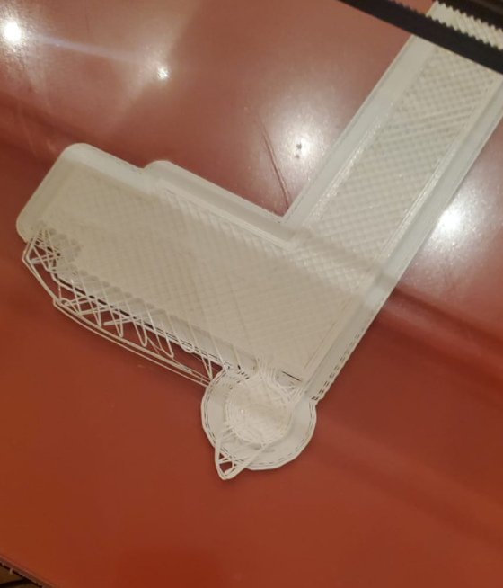
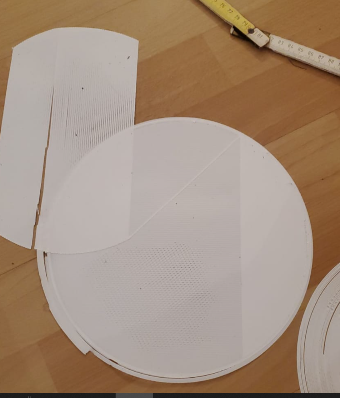
PIC 2: ---Actual settings!
print and shifting for the settings at the moment... I homed x after shift in layer 2 again. ( X shift at layer 2, second shift in Y axis in layer 10)
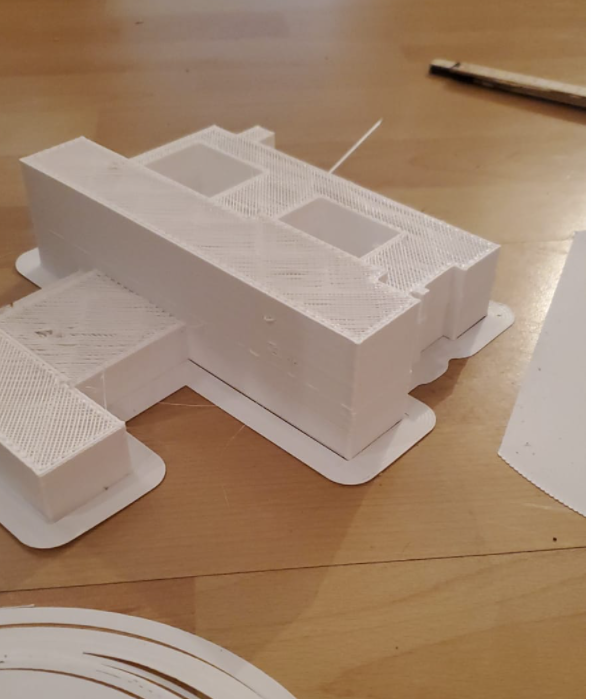
Pic 3:
Older test with shifts which I can saw every round on the position where X has to turn or come to Zero and Accelarate again.
On the left site you can see shaking which was sometimes ended up in shifts. This shaking was in the Y axis motors (both) and sometimes let it stopp X for a small while. Timing was helpful, but there still shifts like you see.
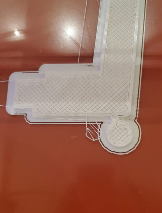
PIC 4
Then I was changing the Timing and that heppened...
The Can connecting till the last board is 11 Meter long, is this a problem?
I changed timing to T10:10:15:15 --> same shifts like before with higher numbers.
@T3P3Tony Do I have really to print in open loop, first?
I was printing with this printer almost 1 Year without bigger problems, no I installed just the 1HCL´s and new motors.Thanks a lot for your replys.
Richard
-
@gruna-studio Changing the settings while the print is progressing may well cause shifts. I have not tested that.
I think it would be good to test in open loop mode. This just requires changing the D parameter of the M569 command. not hardware changes needed.
-
I haven´t changed settings while printing.
just between the prints...So next step print in open loop?
I´´ll write when Test is done...
thanks a lot
-
This post is deleted! -
Also heavy layer shifts in open loop mode.
I was sitting rigth next to it and couldn´t hear any sound for skipping steps.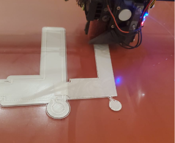
-
-
@gruna-studio said in 1HCL Closed Loop - layer shifts - Timing?:
Problem solved
What was the problem? Loose pulley, perhaps?
Duet WiFi hardware designer and firmware engineer
Please do not ask me for Duet support via PM or email, use the forum
http://www.escher3d.com, https://miscsolutions.wordpress.com -
NO MECHANICAL issue --- of course --- since two weeks I try to solve this problem and it would be very stupid of mine when it would be a pulley. Also I described that different axis are shifting and that the motor is shaking and also just stopping sometims.
I´m sorrybroken expansion board
-
@gruna-studio which, the 1HCL expansion board? How was it broken? We will probably want that back for investigation.
-
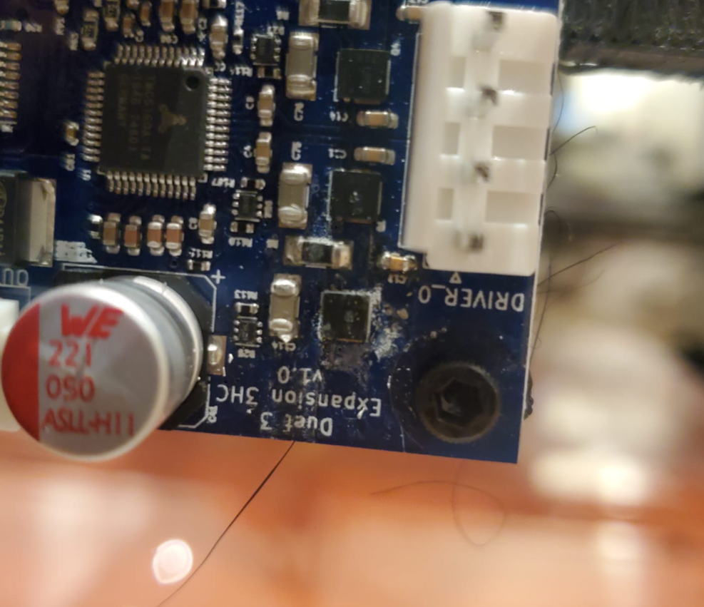
Duet3 3HC expansion board has a small burninig on it. I will send a picture. I haven´t used it before.
But crazy issue for a burned board.Just a last quick question.
How to calculate the steps per mm in closed loop? same way like open loop but no microsteps?
I have a gt2 with 20 teeth = 40 mm
200 steps per revolution / 40 = 5 ----I have 100steps/ mm (which is crazy high) but the models are printed only 20 per cent to big. How can that be?
thanks
Richard -
@gruna-studio
-
@gruna-studio thanks for confirming that - can you email warranty@duet3d.com to arrange a replacement referencing this thread.
I think the issue with microsteps on your setup is because the scaling provided by M350 is still having an impact. 100 steps/mm does not sound right. I expect you have M350 set to 16 (which is the default where microstepping applies) which would be a steps/mm setting of 80 in your setup. (16*5 = 80). If you would prefer to work in full steps then set M350 to 1 and M92 to 5.
edited to add an update:
The microstep setting should be high enough to use the full encoder CPR. e.g. if the encoder is 1000 PPR (so 4000 CPR) and the full steps/rev is 200, then the microstepping needs to be at least 4000/200 = 20 to make use of the full resolution of the encoder.
So in that case I would use M350 X32, and M92 X160 (adjust for the other axis you have with 1HCL.).
-
@gruna-studio I have also updated the documentation page to make this clear:
https://docs.duet3d.com/en/Duet3D_hardware/Duet_3_family/Duet_3_Expansion_1HCL#microstepping -
@t3p3tony
ok great information!!
It´s working great, now. It´s kind of crazy this closed loop system.
thanks for updating the documentation.cheers
richard -
@t3p3tony said in 1HCL Closed Loop - layer shifts - Timing?:
@gruna-studio thanks for confirming that - can you email warranty@duet3d.com to arrange a replacement referencing this thread.
did you see this regarding the damaged expansion board?