DWC Duet Web Control 3.4.0-rc2 no extrude or retract
-
@moth4017 said in DWC Duet Web Control 3.4.0-rc2 no extrude or retract:
M98
Error: M98: No P or R parameterThe command to send is
M98 P"config.g"@moth4017 said in DWC Duet Web Control 3.4.0-rc2 no extrude or retract:
Duet 3 Mini 5+ version 3.4.0rc1
Can you please test with RC2?
https://github.com/Duet3D/RepRapFirmware/releases/download/3.4.0rc2/DuetWebControl-SD.zip
https://github.com/Duet3D/RepRapFirmware/releases/download/3.4.0rc2/Duet3Firmware_Mini5plus.uf2
https://github.com/Duet3D/RepRapFirmware/releases/download/3.3/DuetWiFiServer.bin
-
@phaedrux
Hi had issues updating firmware via DWC
Error: M997: In-application programming binary "0:/firmware/Duet3_SDiap32_Mini5plus.bin" not foundso did the update via usb.
M98 P"config.g"
HTTP is enabled on port 80
FTP is disabled
TELNET is disabledUpdated to rc2

I worked out the issue i did not have any filaments loaded, didn't realise i had to enter a filament , im still not sure why it needs filaments in DWC as all the info comes from the slicer
-
@moth4017 said in DWC Duet Web Control 3.4.0-rc2 no extrude or retract:
Error: M997: In-application programming binary "0:/firmware/Duet3_SDiap32_Mini5plus.bin" not found
You appear to be missing this file.
https://github.com/Duet3D/RepRapFirmware/releases/download/3.3/Duet3_SDiap32_Mini5plus.bin
You should place it in the firmware directory to make future updates possible.
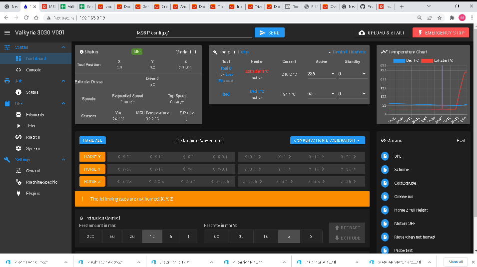
I can't really make out the details in your screen shot. What do you mean by loading a filament?
-
-
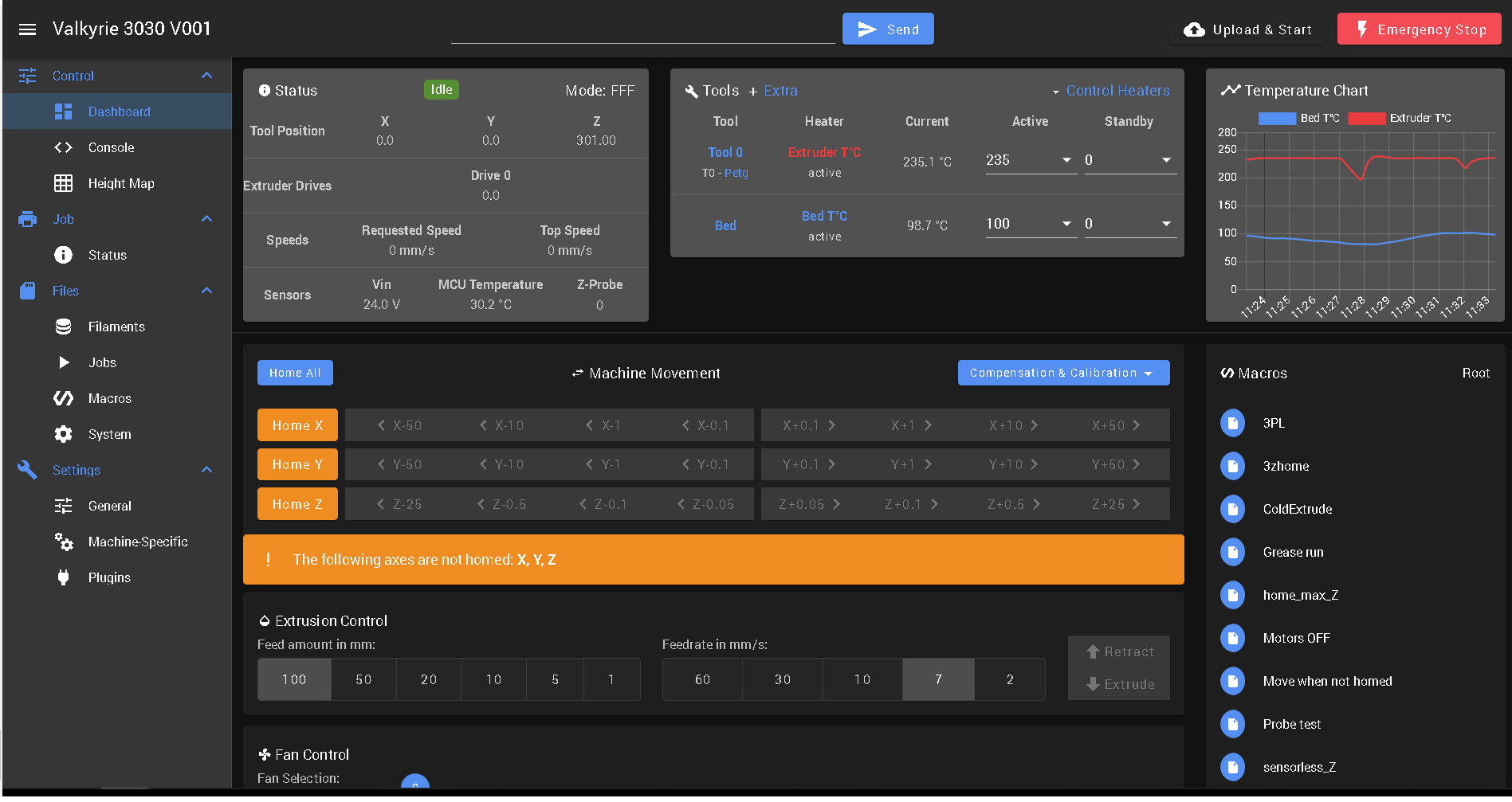
since the new release of 3.4.0 i have this issue again where the retract and extrude is grayed out

; General preferences G90 ; send absolute coordinates... M83 ; ...but relative extruder moves M550 P"Valkyrie 3030 V001" ; set printer name M669 K1 ; core xy ; Network M552 S1 ; enable network M586 P0 S1 ; enable HTTP M586 P1 S0 ; disable FTP M586 P2 S0 ; disable Telnet ; Drives M569 P0.0 S1 ; physical drive 0 goes forwardsM569 P0.1 S1 M569 P0.1 S1 ; physical drive 1 goes forwardsM569 P0.1 S1 M569 P0.2 S1 ; physical drive 2 goes forwards ( blown needs replacing) M569 P0.3 S1 ; physical drive 3 goes forwards (extruder M569 P0.4 S1 D3 V30 ; physical drive 4 goes forwards D3=stealthchop M569 P0.5 S0 D3 V30 ; physical drive 5 goes backwards M569 P0.6 S1 D3 V30 ; physical drive 6 goes forwards M584 X1 Y0 E3 Z0.4:0.5:0.6 ; set drive mapping FL,FR,RC M350 X16 Y16 I1 ; configure microstepping with interpolation M350 Z16 E16 I1 M92 X80.00 Y80.00 Z320.00 E260.00 ; set steps per m M566 X500.00 Y500.00 Z800.00 E100.00 P1 ; set maximum instantaneous speed changes (mm/min) M203 X8000.00 Y8000.00 Z1000.00 E400.00 ; set maximum speeds (mm/min) M201 X1000.00 Y1000.00 Z200.00 E250.00 ; set accelerations (mm/s^2) M906 X1000 Y1000 Z1000 E1400 I10 ; set motor currents (mA) and motor idle factor in per cent M84 S20 ; Set idle timeout ; Axis Limits M208 X0 Y0 Z0 S1 ; set axis minima "Travel Area" M208 X270 Y240 Z405 S0 ; set axis maxima "Travel area" ; Endstops M574 X1 S1 P"!io0.in" ; configure switch-type (e.g. microswitch) endstop for low end on X via pin io0.in M574 Y2 S1 P"!io1.in" ; configure switch-type (e.g. microswitch) endstop for low end on Y via pin io1.in ;M574 Z2 S2 P"!io4.in" ; != invert signal M574 Z2 S4 ; configure sensorless endstop for high end on Z, 1 = low end, 2 = high end. S4 multipule motors M671 X-34.4:296:132.5 Y0:0:296 S25 ; leadscrews at front left,front right, rear Center s= max correction factor must be in same order as M584 M558 P8 C"!io3.in" H5 F600 T18000 A30 S0.03 ; set Z probe type to unmodulated and the dive height + speeds G31 P500 Z0.9 ; set Z probe trigger value, offset and trigger height bigger the posative number the closer to the bed G31 P500 X26 Y6 ; set x,y trigger value, offset and trigger height M557 X30:270 Y10:250 S40 ; define mesh grid ; Heaters M308 S0 P"temp0" Y"thermistor" T100000 B3950 A"Bed T°C" ; configure sensor 0 as thermistor on pin bedtemp M950 H0 C"out0" T0 Q10 ; create bed heater output on bedheat and map it to sensor 0 M307 H0 R0.140 K0.103:0.000 D43.19 E1.35 S0.90 B0 ; PDI info for 8mm aluminium bed 700w Heater NTC 100K 3950 M140 H0 ; map heated bed to heater 0 M143 H0 S120 ; set temperature limit for heater 0 to 120C M308 S1 P"temp1" Y"thermistor" T100000 B4267 A"Extruder T°C" ; configure sensor 1 as thermistor on pin e0temp (104gt2) M950 H1 C"out1" T1 ; create nozzle heater output on e0heat and map it to sensor 1 M307 H1 R3.435 K0.348:0.274 D6.64 E1.35 S1.00 B0 V23.9 ; disable bang-bang mode for heater and set PWM limit M143 H1 S280 ; set temperature limit for heater 1 to 280C ; Fans M950 F0 C"out4" Q500 ; create fan 0 on pin fan0 and set its frequency M106 P0 S0 H-1 ; set fan 0 value. Thermostatic control is turned off M950 F1 C"out3" Q500 ; create fan 1 on pin fan1 and set its frequency M106 P1 S1 H1 T45 ; set fan 1 value. Thermostatic control is turned on ; Tools M563 P0 D0 H1 F0 T0 ; define tool 0 G10 P0 X0 Y0 Z0 ; set tool 0 axis offsets G10 P0 R0 S0 ; set initial tool 0 active and standby temperatures to 0C ; Custom settings are not defined M98 P"/macros/3zhome" -
@moth4017 Where do you select T0? I have a T0 at the bottom of config.g to make sure it's selected.
-
@stephen6309 when i checked in the console which tool i have it has defaulted to T0 , but i have added it now to my config.g now.
Thanks for the reply -
Ok even though the firmware new that the tool T0 was selected adding T0 to the config seems to have fixed this issue.
-
This post is deleted! -
@arnold_r_clark
Ill get some Rat poison

-
same here with 3.4
Found out that you have to select tool active , then it works
