Input shaping guidance
-
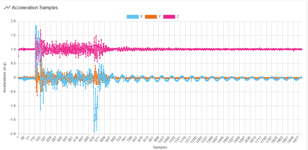
I got my accelerometer connected and working yesterday, and grabbed a bunch of data on moves up to 1G (10K mm/sec^2) and velocities up to 1000mm/sec. Now I'm starting to analyze and looking for a little initial guidance. I'll just use one data set - a 50mm move at 200mm/sec max velocity and 10K max acceleration.
Here''s my raw data and fft graphs:
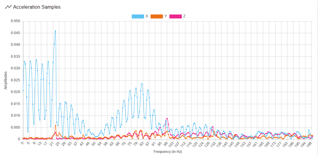
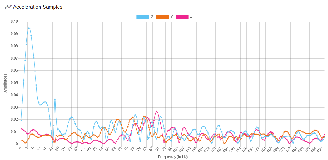
From my reading on the Input Shaping and M593 pages, I think I'd want to target frequencies around 80Hz, or should I worry about all the stuff below 20Hz? The fft for my ludicrous speed (1000mm/sec) does not have the bump around 80Hz, but does have the low frequency stuff. Any specific advice about which P parameter to use in my M593 command, based on this. Or should I just go out to the lab (my garage) and do some test prints?
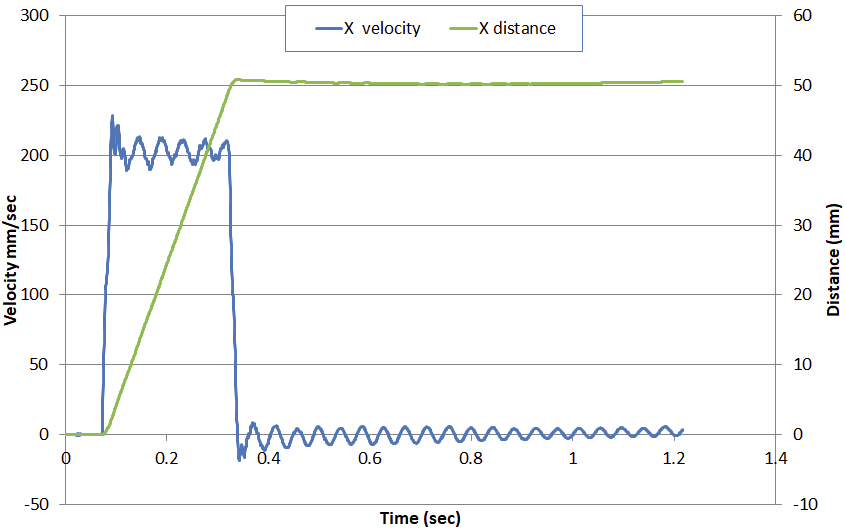
I also (because I can't help myself) too the raw data into excel and did some integration to plot velocity and distances. I was happy to confirm the max speed, acceleration, and distance settings. I can see the low frequency stuff in the velocity line and also in the distance line if I zoom way in - the distance amplitude looks like about 0.1mm p-p. I also found that the accelerometer had a (roughly) constant bias (-0.033g) that I needed to remove to make the graph work. This is my first time using an accel for anything - does this bias make sense?
-
Quick update - I used the sliders on the raw data to isolate on the data after the move stopped and then did the fft again. I have a sharp peak at 22.5Hz. I captured the data again after adding an M593 P"zvd" and in the resulting waveform, that frequency is gone. Super-cool. I'm off to play with a ringing tower.
-
@mikeabuilder The lower frequency peaks in the 20's-30's are typically the ones with the very visible ringing of features and a greater concern. <25Hz are often loose mechanics. I would read the "Technical Details" of the Klipper description @
https://www.klipper3d.org/Resonance_Compensation.htmlYou can add that +- ShaperFreq chart to your excel doc to see which freq to use. Note the Duet also offers ZVDDD with shaper duration 2/Freq.
Short example, ZVD/DD/DDD are +- 15%, you have peaks between about 25.5 and 34. A shaper freq for M593 of 30 would cover the ranges of 25.5 (30*.85) through 34.5 (30*1.15).
-
Last post on this thread - Here's a picture of my ringing tower, lit with a raking light. The first segment was with my previous PA setting turned on. The second band which looks so bad is with no PA and no IS. My IS adjustments are on the left and PA on the right. I ran all but the top two bands at 300mm/sec max and 10K mm/sec^2 max accel. On the second from the top band I increased the accel to 20K and the max speed to 450mm/sec. On the very top band I increased the top speed to 600mm/sec.
Overall I'm really happy with the results. My goal in designing this printer was to better the print speeds from my Anet A8, and that top band jacked up my max speeds by a factor of 10. Duet3D rocks!

-
@mikeabuilder That's interesting, what settings did you finally settle on and how did the PA settings compare to what you had before?
-
@gloomyandy - At present, I'm going to use an S value on the Input Shaper of 0.1 (the default) and a PA value of 0.5 These are the values I set in teh top three bands on the ringing tower in the picture.
I'm running 3.4rc2 firmware and and using the "zvd" type in the Input shaping. I have not tried any other types to see if they might improve the performance.