PanelDue 7 and Duet3 not connecting
-
I have a clone (Fystec) PanelDue 7 based on PanelDue 3.0 design and I'm having trouble getting it to connect. I'm hoping someone can spot something dumb I'm doing (other than buying a clone).
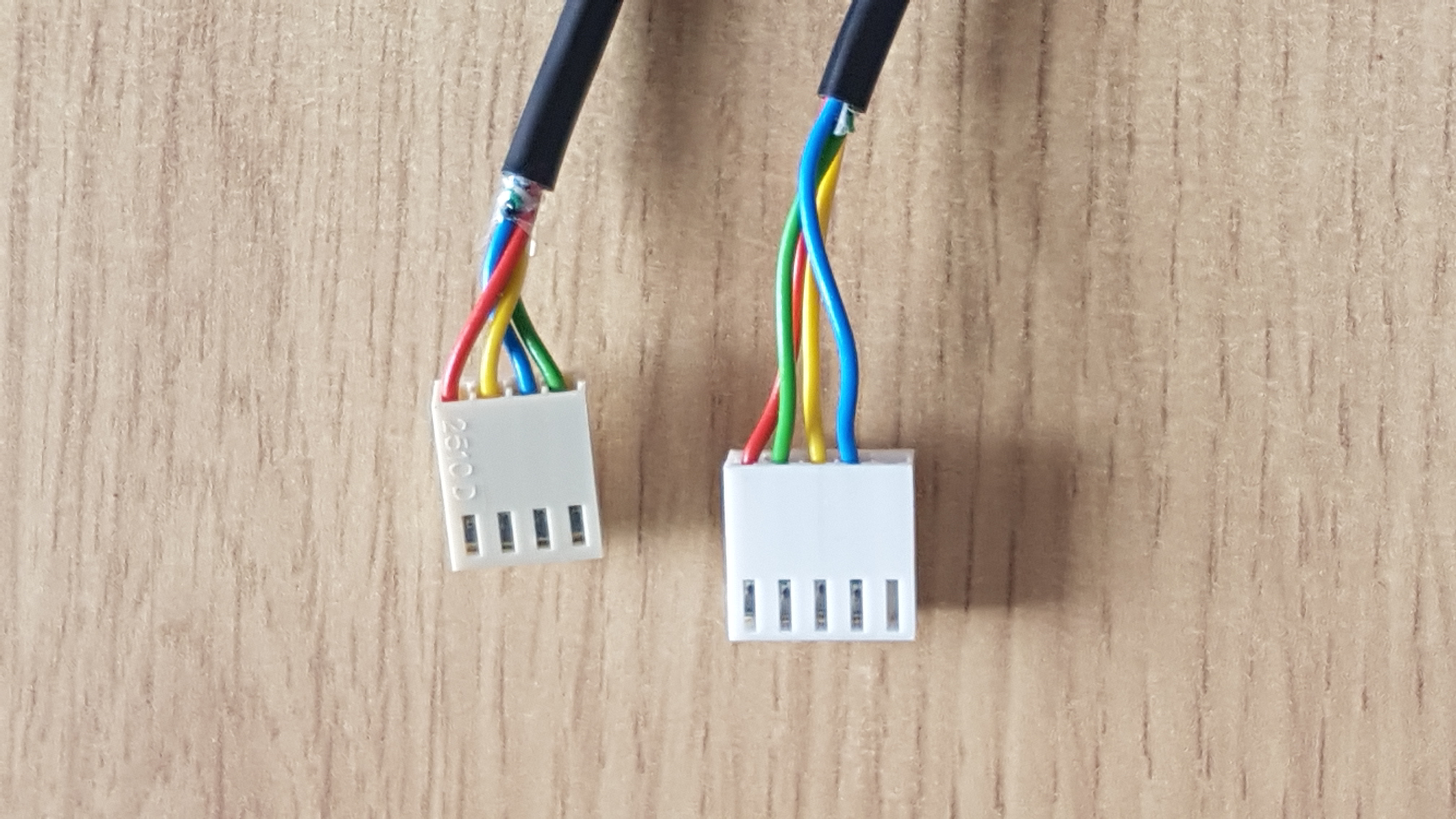
I'm connecting using the 4-wire cable and following the instructions in the doc site.
-
I've got power and ground connected properly because the PanelDue powers on and tries to connect.
-
I've swapped the IO_0.in and IO_0.out wires on the cable. Neither works. My preferred conenction is IO_0.out connected to the RXD on the PanelDue and IO_0.in connected to TXD on the Panel Due. This seems right (I do likethe SPI MISO and MOSI terminology better)
-
I tested the cable connectivity on each wire. All good.
-
I'm connected to IO_0 as required.
-
I have M575 P0 S1 B57600 in my config.g file. I've also tried S0.
-
BAUD rate of 57600 confirmed on the PanelDue.
-
Panel Due fw updated to 3.4.1-pre2.
-
I did a visual inspection of the PanelDue board under magnification. All solder joints look good and no components seem to be missing.
Tomorrow I'll take my panel Due to another printer with one that is working to see if maybe I have a defective clone.
Any other ideas? Do I need an M950 or other command to designate IO_0 as a serial channel? I've looked for this on the doc page but can't find it.
Thanks for any ideas.
-
-
@mikeabuilder can you confirm that you are running firmware 3.4.0 on your main board?
-
And I was trying to be so thorough... Yes, I'm running 3.4.0 on my not-clone MB6HC board.
-
Update - I've plugged the suspect clone PanelDue into another printer (Duet2 WiFi, 3.4.0) and it works fine. I suspect I've got something to fix in my config.g.
I've checked that I've not got io0 assigned in another statement (although I used to use it for an endstop - maybe that previous assignment is retained in fw across reboot cycles?
Complete config.g in case someone suspects somthing else might be amiss.
; Configuration file for Duet 3 (firmware version 3.3) ; executed by the firmware on start-up ; ; generated by RepRapFirmware Configuration Tool v3.3.5 on Sun Nov 07 2021 10:11:11 GMT-0800 (Pacific Standard Time) ; General preferences M929 P"log_file.txt" S1 ; Start loging to log_file and log messages at WARN level or more severe M98 P"0:/sys/create_global_variables.g" G90 ; send absolute coordinates... M83 ; ...but relative extruder moves M550 P"WAP Printer" ; set printer name M555 P0 ; set compatability with RepRap fw M669 K1 ; select CoreXY mode ; Network M552 P0.0.0.0 S1 ; enable network and acquire dynamic address via DHCP M586 P0 S1 ; enable HTTP M586 P1 S0 ; disable FTP M586 P2 S0 ; disable Telnet ; Enable the PanelDue M575 P0 S1 B57600 ; Motors M569 P0.0 S0 ; physical drive 0.0 (Left-rear motor) goes backwards M569 P0.1 S0 ; physical drive 0.1 (Right-rear motor) goes backwards M569 P0.2 S1 ; physical drive 0.2 (Z motor) goes forwards M569 P0.3 S1 ; physical drive 0.3 (Extruder) goes forwards M584 X0.0 Y0.1 Z0.2 E0.3 ; set drive mapping M350 X16 Y16 Z16 E16 I1 ; configure microstepping with interpolation M92 X160.00 Y160.00 Z3200.00 E400 ; set steps per mm (really microsteps per mm) M566 X1800.00 Y1800.00 Z60.00 E120.00 ; set maximum instantaneous speed changes (mm/min) M203 X60000.00 Y60000.00 Z800.00 E800.00 ; set maximum speeds (mm/min) M201 X20000.00 Y20000.00 Z100.00 E250.00 ; set accelerations (mm/s^2) 3/7/22 changed Z from 20 to 100 M906 X2200 Y2200 Z2200 E800 I30 ; set motor currents (mA) and motor idle factor in per cent M84 S30 ; Set idle timeout ; Axis Limits M208 X-2:300 ; {-global.config_X_endstop_offset}:300 ; set X axis Min : max X min will be reset in homex.g M208 Y 0:250 ;{250+global.config_Y_endstop_offset} ; set Y axis Min : max Y max will be reset in homey.g M208 z -4:230 ; {-global.config_Z_negative_limit}:200 ; set Z axis Min : max ; Endstops M574 X1 S1 P"!io2.in" ; configure switch-type (e.g. microswitch) endstop for low end on X via pin io2.in M574 Y2 S1 P"!io1.in" ; configure switch-type (e.g. microswitch) endstop for high end on Y via pin io1.in ;M574 Z1 S2 ; configure BLTouch as the Z endstop ; Z-Probe M950 S0 C"io7.out" ; create servo pin 0 for BLTouch M558 P9 C"io7.in" H5 F120 T6000 ; set Z probe type to bltouch and the dive height + speeds G31 P500 X-31 Y-2 Z2.5 ; set Z probe trigger value, offset and trigger height ; Mesh grid M557 X0:265 Y0:245 P5 ; define mesh grid P5 means 5 x 5 probe grid ; Heaters ;BED HEATER M308 S0 P"temp0" Y"thermistor" T100000 B4138 ; configure sensor 0 as thermistor on pin temp0 M950 H0 C"out0" T0 ; create bed heater output on out0 and map it to sensor 0 M307 H0 R0.100 K0.388:0.000 D3.42 E1.35 S1.00 B0 ; set bed heater parameters M140 H0 ; map heated bed to heater 0 M143 H0 S80 ; set temperature limit for heater 0 to 80C ;EXTRUDER HEATER M308 S1 P"temp1" Y"thermistor" T100000 B4138 ; configure sensor 1 as thermistor on pin temp1 M950 H1 C"out1" T1 ; create nozzle heater output on out1 and map it to sensor 1 M307 H1 R2.772 K0.408:0.000 D4.71 E1.35 S1.00 B0 V22.9 ; set PID parameters fot the extruder heater M143 H1 S280 ; set temperature limit for heater 1 to 280C ; Fans M950 F0 C"out4" Q500 ; create fan 0 on pin out4 and set its frequency M106 P0 S0 H-1 ; set fan 0 value. Thermostatic control is turned off M950 F1 C"out5" Q500 ; create fan 1 on pin out5 and set its frequency M106 P1 S1 H1 T45 ; set fan 1 value. Thermostatic control is turned on ; Tools M563 P0 D0 H1 F0:1 ; define tool 0 (P0), using Extruder 0 (D0), Heater 1 (H1) and Fan 0 (F0) G10 P0 X0 Y0 Z-.7 ; set tool 0 axis offsets G10 P0 R0 S0 ; set initial tool 0 active and standby temperatures to 0C ; Custom settings are not defined ; Set pressure advance to a default value (good for PLA) M572 D0 S0.08 ; set input shaping parameters M593 P"zvd" F23.2 S.1 -
Check closely that you match the wiring for hte Duet 3 as shown here: https://docs.duet3d.com/en/User_manual/Connecting_hardware/Display_PanelDue
-
@mikeabuilder do you get any error messages when you send M98 P"config.g" ?
What response do you get to sending M575 P0 ?
-
@dc42 - When I run M575 P0, I get the following response.
Channel 0: baud rate 57600, requires checksumI assume this tells me that serial channel 0 is enabled and running in Mode 1.
Running your other command - M98 P"config.g" - it throws errors for trying to declare global variables already in existence. But I cleared my log file and restarted via emergency stop. This yielded no errors on console or in the log file. My logging level is S1 (WARN or higher).
I also tried switching my mode M575 Mode to 0 and 4 without and change in the PanelDue Behavior.
I also realized my test yesterday of plugging my PanelDue into another Duet board may not have been valid because I used a ribbon cable for the duet2. Are the ribbon and 4-pin connector on the PanelDue wired to the same serial port?
I'll continue to play with the cabling, but if there's a way to independently verify the function of the serial port on io0, I'd give it a try.
I'm also going to try clipping 3 wires from the ribbon cable and seeing if that works.
-
@mikeabuilder said in PanelDue 7 and Duet3 not connecting:
I also realized my test yesterday of plugging my PanelDue into another Duet board may not have been valid because I used a ribbon cable for the duet2. Are the ribbon and 4-pin connector on the PanelDue wired to the same serial port?
Yes they are.
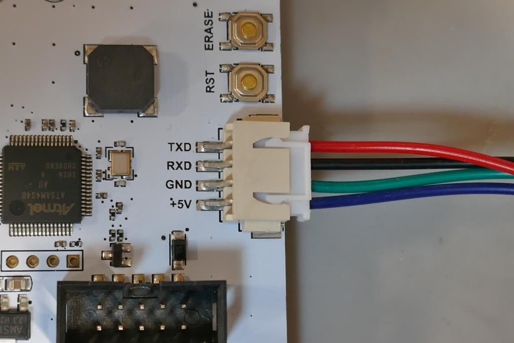
As you used the ribbon cable to connect the PanelDue to your other Duet, the fault may lie with the 4-wire cable. Is your cable wired exactly like this ?

-
I'm the same... now. I've swapped the io0.in and io0.out with each other a few times over the past few days. Looks like this now:

And from the picture, I can confirm the PanelDue RXD (black wire in my photo, blue in yours) connects to the signal io0.In on the io0 connector.

But I've solved it! I did two things and not sure if both were needed or only the second (I suspect only the second).
First - I had been using io_0 as an endstop and had it inverted. I thought maybe the inversion was lingering, so I sent an M950 to not invert the signal. I suspect this made no difference.
Second - RTFM I took a quick triple check of my M575 command against the documentation and noted that in my config.g (above), I have M575 P0 S1 B57600, and the documentation states clearly that it should be M575 P1 S1 B57600.
So a quick change a reboot and it's working! And so is the SDcard connected via the modified ribbon cable.
Thanks to @dc42 and @Phaedrux for your time and energy on this. I'll do penance by trying to help answer some other questions in the forum (I've made enough mistakes to learn a bit).
- Mike
-
 undefined Phaedrux marked this topic as a question
-
 undefined Phaedrux has marked this topic as solved