Configuration of a MCU controlled fan
-
Hi there,
I have problems configuring a MCU temperature dependent fan.
Hardware: One MB3HC6, Two HC3 and a Raspi 4BThis is how the fan is configured:
; System Temperature Sensors
M308 S10 Y"mcu-temp" A"MCU"			; defines sensor 10 as MCU temperature sensor

; Electronic Cooling
M950 F8 C"2.out3" Q65535  				; create fan 8 on pin 2.out3 on MB3HC Board #2 and set its frequency
M106 P8 C"MCU-Fan" T20 H10				; Test MCU TEMP and FAN
The MCU shows a temperature of 40-45°C, but the fan doesn't move.
If I set the fan manually:
M106 P8 C"MCU-Fan" H-1 ; set fan 8 value. Thermostatic control is turned OFFthen I can control it normally.
can it be that the fan must also be connected to the HC6 board, i.e. the board where the temperature is measured?
Second question:
I noticed something else, when I use the rrf config tool, all fans, with a connected sensor, get an H5:XX; Fans for Tool's ; Tool 0 -------------------- ; PartFan for Tool 0 M950 F0 C"out4" Q500 ; create fan 0 on pin out4 and set its frequency M106 P0 C"T0-PF" L0.35 S0 H-1 ; set fan 0 value. Thermostatic control is turned off L0.35 = MinimumSpeed 35% ; HotEnd Fan for Tool 0 M950 F1 C"out5" Q500 ; create fan 1 on pin out5 and set its frequency M106 P1 S1 H5:1 T45 ; set fan 1 value. Thermostatic control is turned on ; Tool 1 -------------------- ; PartFan for Tool 1 M950 F2 C"out6" Q500 ; create fan 2 on pin out6 and set its frequency M106 P2 C"T1-PF" L0.35 S0 H-1 ; set fan 0 value. Thermostatic control is turned off L0.35 = MinimumSpeed 35% ; HotEnd Fan for Tool 1 M950 F3 C"out7" Q500 ; create fan 3 on pin out7 and set its frequency M106 P3 S1 H5:2 T45 ; set fan 3 value. Thermostatic control is turned on ; Tool 2 -------------------- ; PartFan for Tool 2 M950 F4 C"out8" Q500 ; create fan 4 on pin out8 and set its frequency M106 P4 C"T2-PF" L0.35 S0 H-1 ; set fan 0 value. Thermostatic control is turned off L0.35 = MinimumSpeed 35% ; HotEnd Fan for Tool 2 M950 F5 C"out9" Q500 ; create fan 5 on pin out9 and set its frequency M106 P5 S1 H5:3 T45 ; set fan 5 value. Thermostatic control is turned on ; Tool 3 -------------------- ; PartFan for Tool 3 M950 F6 C"1.out3" Q500 ; create fan 6 on pin 1.out3 and set its frequency M106 P6 C"T3-PF" L0.35 S0 H-1 ; set fan 0 value. Thermostatic control is turned off L0.35 = MinimumSpeed 35% ; HotEnd Fan for Tool 3 M950 F7 C"1.out4" Q500 ; create fan 7 on pin 1.out4 and set its frequency M106 P7 S1 H5:4 T45 ; set fan 7 value. Thermostatic control is turned on ;--------------------------------------------------------------------------------The XX is then the right fan, but what does the 5 mean? Because the 5 then stands in front of the actual fan number for all fans. Everything works perfectly (with and without 5), but the 5 doesn't belong there, does it?
-
Can you share your full config.g and the results of m122 and M98 P"config.g" please?
-
@phaedrux
M122:M122 === Diagnostics === RepRapFirmware for Duet 3 MB6HC version 3.4.0 (2022-03-15 18:57:24) running on Duet 3 MB6HC v1.01 or later (SBC mode) Board ID: 08DJM-956BA-NA3TN-6JTDG-3S86J-TUB2T Used output buffers: 1 of 40 (27 max) === RTOS === Static ram: 151000 Dynamic ram: 69104 of which 12 recycled Never used RAM 130556, free system stack 188 words Tasks: SBC(resourceWait:,6.3%,471) HEAT(notifyWait,0.2%,321) Move(notifyWait,0.0%,352) CanReceiv(notifyWait,0.3%,772) CanSender(notifyWait,0.0%,374) CanClock(delaying,0.1%,339) TMC(notifyWait,77.6%,92) MAIN(running,15.4%,923) IDLE(ready,0.1%,30), total 100.0% Owned mutexes: HTTP(MAIN) === Platform === Last reset 03:32:39 ago, cause: power up Last software reset at 2022-04-06 23:13, reason: User, none spinning, available RAM 130480, slot 2 Software reset code 0x0012 HFSR 0x00000000 CFSR 0x00000000 ICSR 0x00400000 BFAR 0x00000000 SP 0x00000000 Task SBC Freestk 0 n/a Error status: 0x00 Aux0 errors 0,0,0 Step timer max interval 134 MCU temperature: min 28.6, current 43.8, max 44.1 Supply voltage: min 23.6, current 23.8, max 24.0, under voltage events: 0, over voltage events: 0, power good: yes 12V rail voltage: min 12.1, current 12.1, max 12.2, under voltage events: 0 Heap OK, handles allocated/used 0/0, heap memory allocated/used/recyclable 0/0/0, gc cycles 0 Events: 0 queued, 0 completed Driver 0: standstill, SG min 0, mspos 8, reads 14753, writes 15 timeouts 0 Driver 1: standstill, SG min 0, mspos 8, reads 14753, writes 15 timeouts 0 Driver 2: standstill, SG min 0, mspos 8, reads 14752, writes 16 timeouts 0 Driver 3: standstill, SG min 0, mspos 8, reads 14752, writes 16 timeouts 0 Driver 4: standstill, SG min 0, mspos 8, reads 14752, writes 16 timeouts 0 Driver 5: standstill, SG min 0, mspos 8, reads 14752, writes 16 timeouts 0 Date/time: 2022-04-08 00:24:38 Slowest loop: 2.76ms; fastest: 0.04ms === Storage === Free file entries: 10 SD card 0 not detected, interface speed: 37.5MBytes/sec SD card longest read time 0.0ms, write time 0.0ms, max retries 0 === Move === DMs created 125, segments created 0, maxWait 0ms, bed compensation in use: none, comp offset 0.000 === MainDDARing === Scheduled moves 0, completed 0, hiccups 0, stepErrors 0, LaErrors 0, Underruns [0, 0, 0], CDDA state -1 === AuxDDARing === Scheduled moves 0, completed 0, hiccups 0, stepErrors 0, LaErrors 0, Underruns [0, 0, 0], CDDA state -1 === Heat === Bed heaters 0 -1 -1 -1 -1 -1 -1 -1 -1 -1 -1 -1, chamber heaters -1 -1 -1 -1, ordering errs 0 === GCodes === Segments left: 0 Movement lock held by null HTTP* is doing "M122" in state(s) 0 Telnet is idle in state(s) 0 File is idle in state(s) 0 USB is idle in state(s) 0 Aux is idle in state(s) 0 Trigger* is idle in state(s) 0 Queue is idle in state(s) 0 LCD is idle in state(s) 0 SBC is idle in state(s) 0 Daemon is idle in state(s) 0 Aux2 is idle in state(s) 0 Autopause is idle in state(s) 0 Code queue is empty === CAN === Messages queued 114774, received 407978, lost 0, boc 0 Longest wait 1ms for reply type 6042, peak Tx sync delay 389, free buffers 50 (min 49), ts 63799/63798/0 Tx timeouts 0,0,0,0,0,0 === SBC interface === Transfer state: 4, failed transfers: 0, checksum errors: 0 RX/TX seq numbers: 39160/39160 SPI underruns 0, overruns 0 State: 5, disconnects: 0, timeouts: 0, IAP RAM available 0x2b880 Buffer RX/TX: 0/0-0, open files: 0 === Duet Control Server === Duet Control Server v3.4.0 Code buffer space: 4096 Configured SPI speed: 8000000Hz, TfrRdy pin glitches: 0 Full transfers per second: 5.60, max time between full transfers: 286.7ms, max pin wait times: 87.3ms/12.8ms Codes per second: 0.00 Maximum length of RX/TX data transfers: 4179/756M98 P"config.g":
M98 P"config.g"
ok
My complete config.g
; CrazyCreatorCube CoreXY ToolChanging Printer - Config File ; inspired from jubilee ; This file intended for Duet 3 hardware, main board plus two expansion boards and a Raspi ; MB6HC6 Mainboard: For XY and Extruders ; EXP_MB3HC #1: For Z ; EXP_MB3HC #2: For Extras ; Name and network ONLY for Info ; This is configured from the connected Raspberry Pi or here if in stand alone mode ;------------------------------------------------------------------------------- ; Networking ;M550 P"CCC" ; Name used in ui and for mDNS http://ccc.local ;M552 P192.168.1.44 S1 ; Use Ethernet with a static IP, 0.0.0.0 for dhcp ;M553 P255.255.255.0 ; Netmask ;M554 192.168.1.1 ; Gateway ; General setup ;------------------------------------------------------------------------------- M111 S0 ; Debug off M929 P"eventlog.txt" S1 ; Start logging to file eventlog.txt ; General Preferences M555 P2 ; Set Marlin-style output G21 ; Set dimensions to millimetres G90 ; Send absolute coordinates... M83 ; ...but relative extruder moves ; Stepper mapping ;------------------------------------------------------------------------------- ; Connected to the MB6HC as the table below. ; Note: first row is numbered left to right and second row right to left ; _______________________________________ ; | Y(Left) 0 | X(Right) 1 | E(T0) 2 | ; | E(T3) 5 | EZ(T2) 4 | E(T1) 3 | M584 X0 Y1 ; X and Y for CoreXY M584 E2:3:4:5 ; E has 4 drivers for 4 Tools ; Connected to the EXP_MB3HC as the table below. ; | Z(Right) 0 | Z(Back) 1 | Z(Left) 2 | ; |-––-––-––-––-––-––-––-––-––-––-––--–| M584 Z1.0:1.1:1.2 ; Z has 3 Drivers for Kinematic bed, connected to first MB3HC ; ToolChanger-Lock-Drive (C) and in Future the WasteMotors, connected to second MB3HC M584 C2.0 ; M569: Set motor driver direction, enable polarity and step pulse timing on MB6HC M569 P0 S0 ; Drive 0 | X stepper M569 P1 S0 ; Drive 1 | Y Stepper M569 P2 S0 D2 ; Drive 2 | Extruder T0 1400mA Spreadcycle Mode M569 P3 S0 D2 ; Drive 3 | Extruder T1 1400mA Spreadcycle Mode M569 P4 S0 D2 ; Drive 4 | Extruder T2 1400mA Spreadcycle Mode M569 P5 S0 D2 ; Drive 5 | Extruder T3 1400mA Spreadcycle Mode ; Connected to EXP_MB3HC #1 M569 P1.0 S0 ; Drive 1.0 | Front Right Z M569 P1.1 S0 ; Drive 1.1 | Back Z M569 P1.2 S0 ; Drive 1.2 | Front Left Z ; Connected to EXP_MB3HC #2 M569 P2.0 S0 ; Drive 2.0 | Coupler ;M569 P2.1 S0 ; Drive 2.1 | UNUSED - Planed for Wastebox ;M569 P2.2 S0 ; Drive 2.2 | UNUSED - Planed for Wastebox ; M906: Set motor currents M906 X{0.7*sqrt(2)*2000} I30 ; LDO XY 2000mA RMS LDO 0.9° Stepper Motor| LDO-42STH60-MAC the TMC5160 driver on duet3 generates a sinusoidal M906 Y{0.7*sqrt(2)*2000} I30 ; coil current so we can multiply by sqrt(2) to get peak used for M906. Do not exceed 90% without heatsinking the XY steppers. ; {0.7*sqrt(2)*1400} 70% of 1400mA E don't support expressions in 3.2.0-beta4 M906 E1400 C500 I10 ; Set Currents for E (Extruder) and C (Coupler) Motors M906 Z{0.7*sqrt(2)*1680} I30 ; 70% of 1680mA RMS. Note that the idle will be shared for all drivers - LDO 0.9° Stepper Motor | LDO-42STH48-MAC ; Kinematics ;------------------------------------------------------------------------------- M669 K1 ; CoreXY mode ; Kinematic bed ball locations. ; Locations are extracted from CrazyCreatorCube-CAD model assuming lower left build plate corner ; is (0, 0) on a 350x350mm plate. This mean the Kinematic Bed Ball Connectors. M671 X361:171:-19 Y5.5:358.5:-5.5 S100 ; Front Right: (X361, Y5.5) 0 ; Back Middle: (X171, Y358.5) 1 ; Front Left: (X-19, Y-5.5) 2 ; Up to 100mm correction ; __________________________________________ ; |Y| |X| ; ------------------------------------------ ; ||| |E0| |E1| |Z1| |E2| |E3| ||| ; ||| ||| ; ||| ||| ; ||| ||| ; ||| ||| ; ||| ||| ; ||| ||| ; ||| ||| ; ||| ||| ; |||Z2| |Z0||| ; Axis and motor configuration ;------------------------------------------------------------------------------- M350 X1 Y1 Z1 E1:1:1:1 ; Disable microstepping to simplify calculations M92 X{1/(0.9*20/180)} ; step angle * tooth count / 180 M92 Y{1/(0.9*20/180)} ; The 2mm tooth spacing cancel out with diam to radius M92 Z{360/0.9/4} ; 0.9 deg stepper / lead (4mm) of screw M92 E51.875:55:60:70 ; 51.875 = BMG-Extruder with 0.9 deg/stepper-motor M92 C91.022 ; E3D-Coupler-Drive ; Enable microstepping all step per unit will be multiplied by the new step def M350 X16 Y16 I1 ; 16x microstepping for CoreXY axes. Use interpolation. M350 Z16 I1 ; 16x microstepping for Z axes. Use interpolation. M350 E16:16:16:16 I1 ; 16x microstepping for Extruder axes. Use interpolation. M350 C16 I10 ; 16x microstepping. Without interpolation. ; Acceleration, Speed and Jerk ;------------------------------------------------------------------------------- ; Acceleration - (mm/s^2) / TitanAero: E5000.00 / Orbiter:E600 M201 X1100 Y1100 ; Accelerations (mm/s^2) M201 Z100 ; LDO ZZZ Acceleration M201 E1300 ; Extruder M201 C500 ; Coupler Motor ; Speed M203 X18000 Y18000 Z1000 E8000 C5000 ; Maximum axis speeds (mm/min) ; Jerk - Set maximum instantaneous speed changes (mm/min) M566 X500 Y500 Z500 C2 E3000 ; Maximum jerk speeds (mm/min) ; Endstops and probes ;------------------------------------------------------------------------------- ; Connected to the MB6HC as the table below. ; | | | ; | X | | ; | Y | | ; Endstops M574 X1 S1 P"io1.in" ; Configure active-high endstop for low end on X via pin io1.in M574 Y1 S1 P"io2.in" ; configure active-high endstop for low end on Y via pin io2.in M574 Z1 S2 ; configure Z-probe endstop for low end on Z M574 C0 ; NO Endstop for C-Coupler ; Z-Probe M558 P8 C"^1.io1.in" H5 F800 T10000 ; set Z probe type to switch and the dive height + speeds / In Jubilee P5 but not supported on Expansion Board G31 P500 X0 Y0 Z2.5 ; set Z probe trigger value, offset and trigger height ; Set axis software limits and min/max switch-triggering positions. ; Must be adjusted so that X=0 and Y=0 coordinates are at the left front corner of the print bed ; Axis Minima:Maxima M208 X-23:380 Y-13:371 Z0:320 C-45:360 ; Define Mesh Grid and Probing Points distance M557 X30:360 Y15:330 P5 ; define mesh grid ; Heaters and temperature sensors ;------------------------------------------------------------------------------- ; Bed M308 S0 P"1.temp0" Y"thermistor" T100000 B4138 A"Heizbett" ; configure sensor 0 as thermistor on pin 1.temp0 M950 H0 C"1.out0" T0 ; create bed heater output on 1.out0 and map it to sensor 0 M307 H0 B0 S1.00 ; disable bang-bang mode for the bed heater and set PWM limit M140 H0 ; map heated bed to heater 0 M143 H0 S140 ; set temperature limit for heater 0 to 140C ; Tools - Nozzle Heater Configuration ; Tool 0 M308 S1 P"temp0" Y"thermistor" T100000 B4725 C7.06e-8 ; configure sensor 1 as thermistor on pin temp0 M950 H1 C"out0" T1 ; create nozzle heater output on out1 and map it to sensor 1 M307 H1 B0 S1.00 ; disable bang-bang mode for heater and set PWM limit M143 H1 S280 ; set temperature limit for heater 1 to 280C ; Tool 1 M308 S2 P"temp1" Y"thermistor" T100000 B4725 C7.06e-8 ; configure sensor 2 as thermistor on pin temp1 M950 H2 C"out1" T2 ; create nozzle heater output on out2 and map it to sensor 2 M307 H2 B0 S1.00 ; disable bang-bang mode for heater and set PWM limit M143 H2 S280 ; set temperature limit for heater 2 to 280C ; Tool 2 M308 S3 P"temp2" Y"thermistor" T100000 B4725 C7.06e-8 ; configure sensor 3 as thermistor on pin temp2 M950 H3 C"out2" T3 ; create nozzle heater output on out3 and map it to sensor 3 M307 H3 B0 S1.00 ; disable bang-bang mode for heater and set PWM limit M143 H3 S280 ; set temperature limit for heater 3 to 280C ; Tool 3 M308 S4 P"temp3" Y"thermistor" T100000 B4725 C7.06e-8 ; configure sensor 4 as thermistor on pin temp3 M950 H4 C"out3" T4 ; create nozzle heater output on out3 and map it to sensor 4 M307 H4 B0 S1.00 ; disable bang-bang mode for heater and set PWM limit M143 H4 S280 ; set temperature limit for heater 4 to 280C ; System Temperature Sensors M308 S10 Y"mcu-temp" A"MCU" ; defines sensor 10 as MCU temperature sensor ;M308 S11 Y"drivers" A"Drivers" ; defines sensor 11 as stepper driver temperature sensor / Don't work on Duet3 with Trinamic-Drivers ; Fans ;------------------------------------------------------------------------------- ; Fans for Tool's ; Tool 0 -------------------- ; PartFan for Tool 0 M950 F0 C"out4" Q500 ; create fan 0 on pin out4 and set its frequency M106 P0 C"T0-PF" L0.35 S0 H-1 ; set fan 0 value. Thermostatic control is turned off L0.35 = MinimumSpeed 35% ; HotEnd Fan for Tool 0 M950 F1 C"out5" Q500 ; create fan 1 on pin out5 and set its frequency M106 P1 S1 H5:1 T45 ; set fan 1 value. Thermostatic control is turned on ; Tool 1 -------------------- ; PartFan for Tool 1 M950 F2 C"out6" Q500 ; create fan 2 on pin out6 and set its frequency M106 P2 C"T1-PF" L0.35 S0 H-1 ; set fan 0 value. Thermostatic control is turned off L0.35 = MinimumSpeed 35% ; HotEnd Fan for Tool 1 M950 F3 C"out7" Q500 ; create fan 3 on pin out7 and set its frequency M106 P3 S1 H5:2 T45 ; set fan 3 value. Thermostatic control is turned on ; Tool 2 -------------------- ; PartFan for Tool 2 M950 F4 C"out8" Q500 ; create fan 4 on pin out8 and set its frequency M106 P4 C"T2-PF" L0.35 S0 H-1 ; set fan 0 value. Thermostatic control is turned off L0.35 = MinimumSpeed 35% ; HotEnd Fan for Tool 2 M950 F5 C"out9" Q500 ; create fan 5 on pin out9 and set its frequency M106 P5 S1 H5:3 T45 ; set fan 5 value. Thermostatic control is turned on ; Tool 3 -------------------- ; PartFan for Tool 3 M950 F6 C"1.out3" Q500 ; create fan 6 on pin 1.out3 and set its frequency M106 P6 C"T3-PF" L0.35 S0 H-1 ; set fan 0 value. Thermostatic control is turned off L0.35 = MinimumSpeed 35% ; HotEnd Fan for Tool 3 M950 F7 C"1.out4" Q500 ; create fan 7 on pin 1.out4 and set its frequency M106 P7 S1 H5:4 T45 ; set fan 7 value. Thermostatic control is turned on ;-------------------------------------------------------------------------------- ; Fans for Electronic M950 F8 C"2.out3" Q65535 ; create fan 8 on pin 2.out3 on MB3HC Board #2 and set its frequency ;M106 P8 C"MCU-Fan" H-1 ; set fan 8 value. Thermostatic control is turned OFF M106 P8 C"MCU-Fan" T20 H10 ; Test MCU TEMP and FAN ; Lightning on FAN Port M950 F9 C"2.out0" Q100 ; Fan 10 (Mean the COB-LED-Stripe) is connected to 2.out0 on the second Exp_3HC Board M106 P9 S0.15 C"Light" H-1 ; Set Fan 10 values: Start at 15% / Name in DWC / Thermostatic control turned OFF ; Tool definitions ;------------------------------------------------------------------------------- ;M563 P0 S"Tool 0" D0 H1 F5 ; Px = Tool number / Dx = Drive Number / H1 = Heater Number / Fx = Fan number print cooling fan ;G10 P0 R0 S0 ; Set tool 0 operating and standby temperatures / (-273 = "off") M563 P0 S"Tool0" D0 H1 F0 ; define tool 0 G10 P0 R0 S0 ; set initial tool 0 active and standby temperatures to 0C M563 P1 S"Tool1" D1 H2 F2 ; define tool 1 G10 P1 R0 S0 ; set initial tool 1 active and standby temperatures to 0C M563 P2 S"Tool2" D2 H3 F4 ; define tool 2 G10 P2 R0 S0 ; set initial tool 2 active and standby temperatures to 0C M563 P3 S"Tool3" D3 H4 F6 ; define tool 3 G10 P3 R0 S0 ; set initial tool 3 active and standby temperatures to 0C ;-------------------------------------------------------------------------------- ; Set extruder pressure advance ;M572 D0 S0.085 ; Set extruder 0 Pressure Advance to 0.085 seconds ;M572 D1 S0.085 ; Set extruder 1 Pressure Advance to 0.085 seconds ;M572 D2 S0.085 ; Set extruder 2 Pressure Advance to 0.085 seconds ;M572 D3 S0.085 ; Set extruder 3 Pressure Advance to 0.085 seconds ; Tool XYZ Offsets for each Tool M98 P"/sys/Toffsets.g" ; Set tool offsets from the bed ; Miscellaneous ;------------------------------------------------------------------------------- M575 P1 S1 B57600 ; enable support for PanelDue M501 ; load saved parameters from non-volatile memory M911 S10 R11 P"M913 X0 Y0 G91 M83 G1 Z3 E-5 F1000" ; set voltage thresholds and actions to run on power loss -
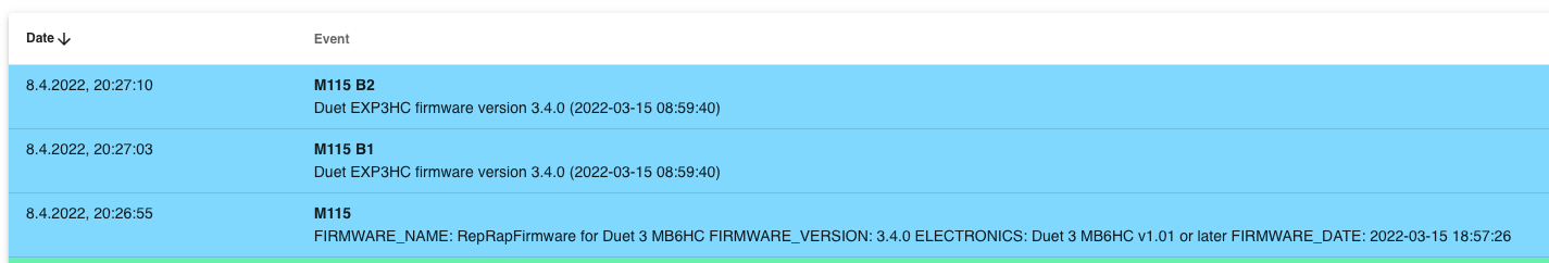
@crazycreator please check that the 3HC board is also running firmware 3.4, because this combination (fan connected to an expansion board and temperature sensor connected to a different board) was a known limitation of firmware 3.3. See https://docs.duet3d.com/en/User_manual/RepRapFirmware/CAN_limitations.
-
-
@crazycreator thanks. I've logged this as a possible bug for investigation.
-
@dc42 thank you ...
-
@crazycreator I believe this is fixed in RRF 3.4.2rc2 which has been released today.
-
Thanks for the tip...
I've already installed the update, but haven't gotten around to testing it again yet.