It works ")
Best posts made by CrazyCreator
-
RE: Update to 3.4.2-rc3posted in Firmware installation
@jay_s_uk Damn ... those who can read have a clear advantage
-
RE: Fly-SHT36 Max V3 RP2040 Based CAN-FD Toolboardposted in RepRapFirmware on other controllers
@jay_s_uk
Many thanks for your support ... i think i write the next days for config the new z-probe-scanner
-
RE: Update to 3.4.0 beta 7posted in Firmware installation
@dc42
now the update is visible and working -
RE: Fly-SHT36 Max V3 RP2040 Based CAN-FD Toolboardposted in RepRapFirmware on other controllers
@jay_s_uk
Oh dear... How could I have forgotten that? I put the MOSFET in a small bowl so I wouldn't forget it!!!Now the fan works too
")
-
RE: Flashing firmware on Mac OS Xposted in Firmware installation
@droftarts said in Flashing firmware on Mac OS X:
@blacksheep99 Do you mean when you downloaded the zip file from Github it automatically extracted it? That's a browser setting. If you're using Safari, from the menus select Safari > Preferences, and untick the 'Open "safe" files after downloading' on the General tab. Zip files will then not automatically extract. Other browsers have this 'feature' optionally set in preferences, too.
or go in the waste box and drag&drop to desktop
-
RE: Fan Wiring on Duet 2 Wifiposted in General Discussion
hello jay my friend
Does that sound like everything is completely normal and intentional?
So is not a bug ... but a feature
-
RE: [DSF Extension] Exec On MCode (was: Shutdown SBC)posted in DSF Development
With the new release 3.3RC3 it works
Now I have to put the code for power off the shelly-pm in my shutdownsbc.service
next adventure for me
Latest posts made by CrazyCreator
-
RE: Fly-SHT36 Max V3 RP2040 Based CAN-FD Toolboardposted in RepRapFirmware on other controllers
@CrazyCreator
For anyone who has the same problem after me, here's how to connect or insert the ribbon cable.
You have to flip the small black bracket upwards, then insert the cable, and then flip the bracket back down. This secures the cable.
Of course, you should have known beforehand that there is a bracket on these mini jacks.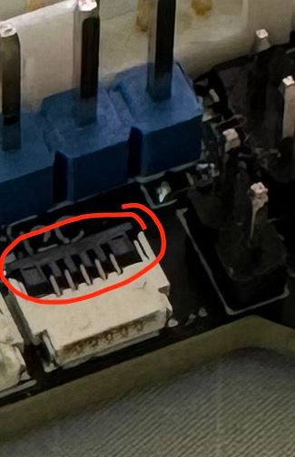
-
RE: Fly-SHT36 Max V3 RP2040 Based CAN-FD Toolboardposted in RepRapFirmware on other controllers
@jay_s_uk and maybe @jumpedwithbothfeet said in Fly-SHT36 Max V3 RP2040 Based CAN-FD Toolboard:
... , watch out for the ribbon connectors I found them quite tricky!
I managed to get the ribbon cable in on the side of the probe, but on the board itself... No chance. It doesn't slide in deep enough to stay in place. It keeps falling out.

Do you have any tips that might make this easier or even possible?
Is there nothing on the socket itself that you need to unlock or open before inserting the ribbon cable?
-
RE: Fly-SHT36 Max V3 RP2040 Based CAN-FD Toolboardposted in RepRapFirmware on other controllers
@jay_s_uk
Can you help me again?When I send the MicroProbe to probe the bed, it moves to the planned point and the pin pops out briefly but then goes back in immediately
and the bed stops.
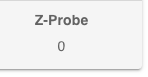
The DWC Show: Z-Probe 0
Then the error message appears:
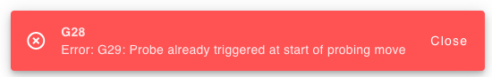
The config.g for this:; Endstops M574 X1 S1 P"!124.io1.in" ; configure switch-type (e.g. microswitch) endstop for low end on X via pin 124.io1.in on Fly-SHT36 Max V3 M574 Y1 S1 P"!io2.in" ; configure switch-type (e.g. microswitch) endstop for low end on Y via pin io2.in on MB6HC M574 Z1 S2 ; configure Z-probe endstop for low end on Z on Fly-SHT36 Max V3 ; Z-Probes ; Configuration for Z-Probe - BTT BiQu MicroProbe V2 M558 P9 H6 F250:30 T8000 C"^124.io0.in" ; set Z probe type to microprobe and the dive height + speeds M950 P0 C"124.io0.out" ; Setup io0.out as on/off port on Fly-SHT36 Max V3 G31 P500 X30.01 Y48.6 Z0.7 ; set Z probe trigger value, offset and trigger height ; Configuration for Scanning Probe from SHT36 ;M558 K1 P11 C"124.i2c.ldc1612" H5 F120 T6000 ; configure scanning probe via slot #1 ;G31 P500 X0 Y0 Z0.7 ; set Z probe trigger value, offset and trigger height ; Define Mesh Grid and Probing Points distance M557 X30:300 Y15:250 P5 ; define mesh gridWhen i try the other way in config.g with !
; Endstops
M574 X1 S1 P"!124.io1.in"                                                               ; configure switch-type (e.g. microswitch) endstop for low end on X via pin 124.io1.in on Fly-SHT36 Max V3
M574 Y1 S1 P"!io2.in"                                                                   ; configure switch-type (e.g. microswitch) endstop for low end on Y via pin io2.in on MB6HC
M574 Z1 S2                                                                              ; configure Z-probe endstop for low end on Z on Fly-SHT36 Max V3

; Z-Probes
; Configuration for Z-Probe - BTT BiQu MicroProbe V2
M558 P9 H6 F250:30 T8000 C"^!124.io0.in"                                                ; set Z probe type to microprobe and the dive height + speeds
M950 P0 C"124.io0.out"                                                                  ; Setup io0.out as on/off port on Fly-SHT36 Max V3
G31 P500 X30.01 Y48.6 Z0.7                                                              ; set Z probe trigger value, offset and trigger height

; Configuration for Scanning Probe from SHT36
;M558 K1 P11 C"124.i2c.ldc1612" H5 F120 T6000                                           ; configure scanning probe via slot #1
;G31 P500 X0 Y0 Z0.7                                                                    ; set Z probe trigger value, offset and trigger height

; Define Mesh Grid and Probing Points distance
M557 X30:300 Y15:250 P5                                                                 ; define mesh grid
If I connect it like this, the MicroProbe works. The pin pops out and is triggered by the bed, and the bed stops.
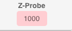
BUT then I see a red 1000 on the display.

But the homing works perfectly fine, even though it says 1000 in red. That's kind of surprising, because that's not how it's supposed to be, is it?
Maybe you can take a look at my configuration?
Attached are config.g and the homing files:
config.g
homeall.g
homex.g
homey.g
homez.gMaybe
-
RE: Fly-SHT36 Max V3 RP2040 Based CAN-FD Toolboardposted in RepRapFirmware on other controllers
@jay_s_uk
That will be the next project. Calibrating the scanner... Yeaaaaah -
RE: Fly-SHT36 Max V3 RP2040 Based CAN-FD Toolboardposted in RepRapFirmware on other controllers
@jay_s_uk Hello ... Ready now

MicroProbe and Proximity Sensor connected and working (in Testconfig).
Only if you interested, there the part from config.g
; Endstops M574 X1 S1 P"!124.io1.in" ; configure switch-type (e.g. microswitch) endstop for low end on X via pin 124.io1.in on Fly-SHT36 Max V3 M574 Y1 S1 P"!io2.in" ; configure switch-type (e.g. microswitch) endstop for low end on Y via pin io2.in on MB6HC M574 Z1 S2 ; configure Z-probe endstop for low end on Z on Fly-SHT36 Max V3 ; Z-Probes ; Configuration for Z-Probe - BTT BiQu MicroProbe V1 M558 P9 H6 F250:30 T8000 C"^124.io0.in" ; set Z probe type to microprobe and the dive height + speeds M950 P0 C"124.io0.out" ; Setup 124.io0.out as on/off port on Fly-SHT36 Max V3 G31 P500 X0 Y0 Z0.7 ; set Z probe trigger value, offset and trigger height ; Configuration for Scanning Probe from SHT36 M558 K1 P11 C"124.i2c.ldc1612" H5 F120 T6000 ; configure scanning probe via slot #1 G31 P500 X0 Y0 Z0.7 ; set Z probe trigger value, offset and trigger height ; Define Mesh Grid and Probing Points distance M557 X30:360 Y15:330 P5 ; define mesh grid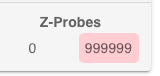 I think this is normal, because the Scanning Probe is not connected?
 -
RE: Fly-SHT36 Max V3 RP2040 Based CAN-FD Toolboardposted in RepRapFirmware on other controllers
@jay_s_uk
It's this sensor: https://s.click.aliexpress.com/e/_oo1zqJ5And it's connected like this:
-
RE: Fly-SHT36 Max V3 RP2040 Based CAN-FD Toolboardposted in RepRapFirmware on other controllers
Today I finally got back to my printer
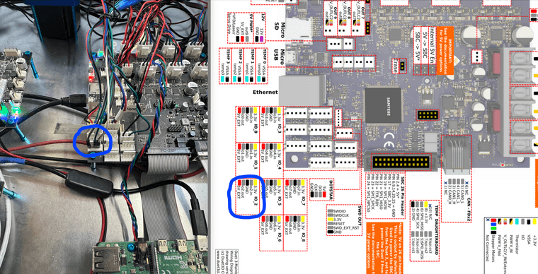
and have a little bit of work ahead of me for tomorrow.I would like to connect a GL-8FN1 sensor as an X-Endstop to the SHT36.
Unfortunately, I've only found these two options:
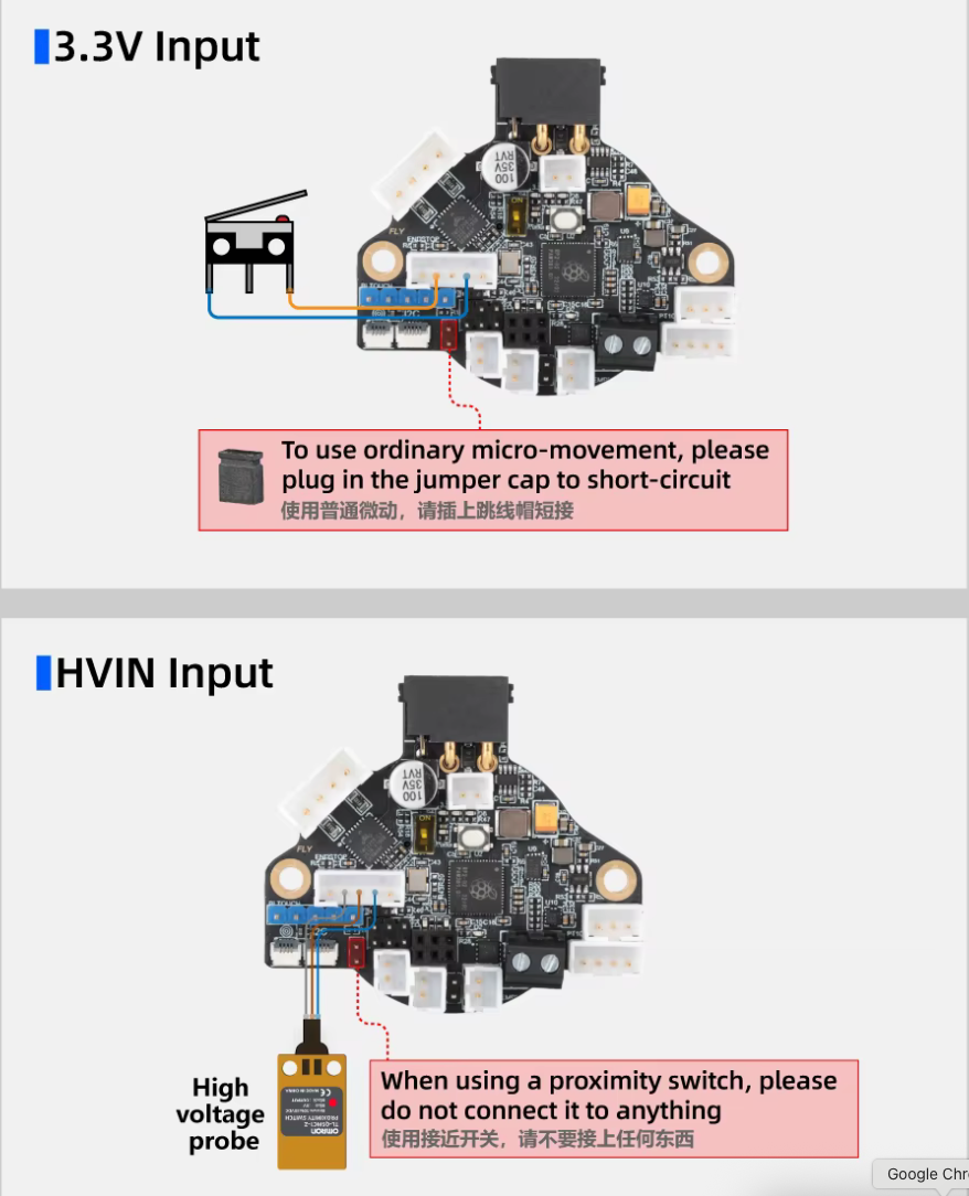
And now I'm not sure if the "HVIN" input corresponds to my sensor.I'm already using the same sensor as a Y-Endstop. It's connected to the MB6HC, of course:
M574 Y1 S1 P"!io2.in" ; configure switch-type (e.g., microswitch) endstop for low end on Y via pin io2.inUnfortunately, I'm currently a bit unsure about which pins I should use on the SHT36.
-
RE: Fly-SHT36 Max V3 RP2040 Based CAN-FD Toolboardposted in RepRapFirmware on other controllers
@jay_s_uk Currently, all 8 jumpers are plugged in. I think that's correct, right?
-
RE: Fly-SHT36 Max V3 RP2040 Based CAN-FD Toolboardposted in RepRapFirmware on other controllers
So... Let's move on
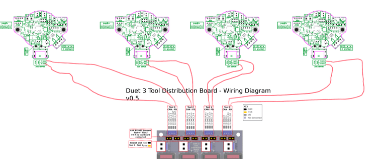
Since the SHT36 is working so well, I got a toolboard yesterday and now want to connect 4 SHT36s to it.
Is the CAN wiring in my ugly drawing correct?