Enabling Dual Filament Runout Sensor
-
Hello all,
We are using BTT Octopus Pro board for Single extruder and for IDEX machines.
We are using RRF. (RepRapFirmware for STM32F4 based Boards 3.3.0_11 (2021-11-04))
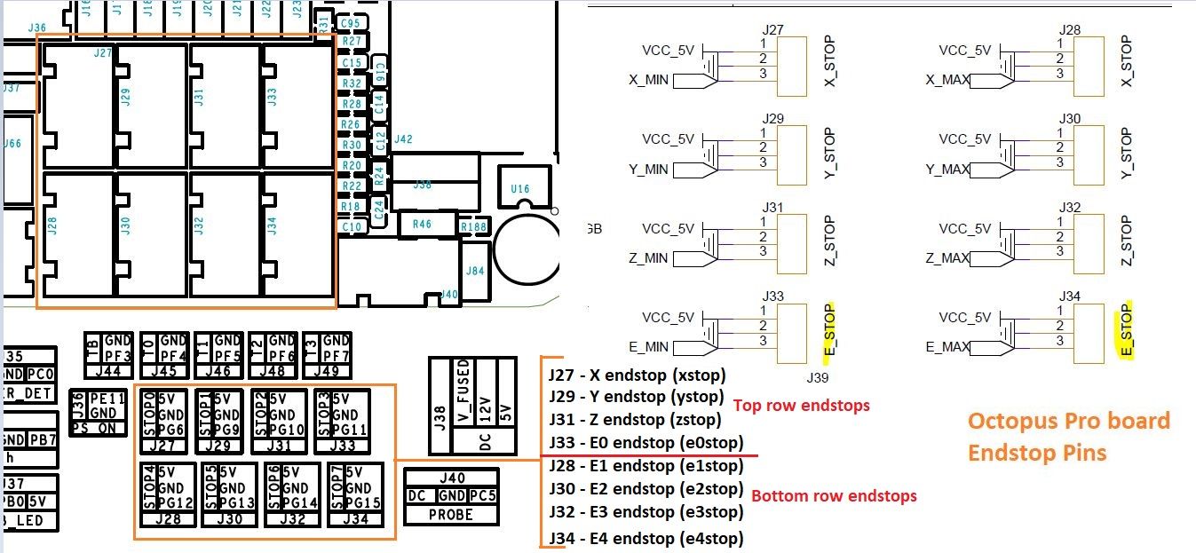
For Single extruder machine, we are connecting the Filament Runout sensor (3 Pin Mechanical Endstop) in the e0stop pin and given the below code:
M591 D0 P1 C"e0stop" S1Whenever there is no filament, the print pauses and gives the warning 'No filament' (Both in TFT as well as in DWC). It is working perfectly.
In IDEX, we connected the Left side extruder FRS to e1stop pin and tried to use the below command:
M591 D0 P1 C"e1stop" S1We used the M591 D0 to see the status:
'Simple filament sensor on pin (e1stop,e1det), enabled, output low when no filament, filament present: yes'When we remove the filament, it is not trigerring and it shows the same message as above. Always shows the filament present as 'yes' only
Also, how can we connect the Right extruder FRS and what will be the configuaration?
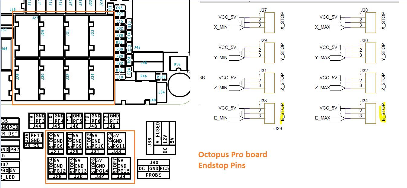
Is it possible to use the X_max endstop for U axis. If yes, what can be given in M591.
Thanks in advance
-
@selva_tvi if you post the config.g of your IDEX we can see how you've currently defined everything. Then we can go from there
Owns various duet boards and is the main wiki maintainer for the Teamgloomy LPC/STM32 port of RRF. Assume I'm running whatever the latest beta/stable build is
-
@selva_tvi I presume that one of your print heads uses extruder 0 and the other uses extruder 1. The extruder number(s) are defined by the D parameters in the M563 tool creation commands in config.g. The D parameter in the M591 command to create a filament monitor defines which extruder it is associated with.
Duet WiFi hardware designer and firmware engineer
Please do not ask me for Duet support via PM or email, use the forum
http://www.escher3d.com, https://miscsolutions.wordpress.com -
-
@dc42 Thanks. I have already used M591 command for a single extruder machine and it is working finely. In this, Filament monitor was connected to 'e0stop'
But coming to IDEX, already U axis is connected to 'e0stop', so I have to connect the FRS to 'e1stop'. Is there any way to connect the FRS to Xmax or Ymax endstops as per the above diagram?
-
@jay_s_uk Kindly check and update on this.
-
@selva_tvi We got the solution. Pin assignment in config.g has to be changed.
;Filament Runout sensor
M591 D0 P1 C"e1stop" S1
M591 D1 P1 C"e2stop" S1Accordingly it has to be connected to the board as per the given diagram
We can consider this as solved and we can close this case. Thanks for the support