Euclid probe and Z=0 datum
-
@dhusolo said in Euclid probe and Z=0 datum:
@fcwilt @fcwilt I used the macro templates from the Euclid probe website.
OK - I will check them out and talk with the author.
I have a railcore 250zl bed with independent leveling with kinematic mounts. I don't really have to deal with bed droppage too much. After I built it I ran numerous rounds of leadscrew leveling and the values were very consistent.
Good to know.
I've never had to use G30 S-2. I wasn't sure if it was because of the Euclid probe, a firmware issue, config issue or what the deal is. I've never had this happen before.
Well something is not configure correctly and it is not related to the Euclid probe.
When you used a plain G30 what was the result the led you to try G30 S-2?
Thanks.
Frederick
Printers: a small Utilmaker style, a small CoreXY and a E3D MS/TC setup. Various hotends. Using Duet 3 hardware running 3.4.6
-
@fcwilt G30 S-2 sets Z0 where the probe triggered. Probes don't trigger the same distance when the nozzle hits the bed, unless the hotend triggers the probe.
-
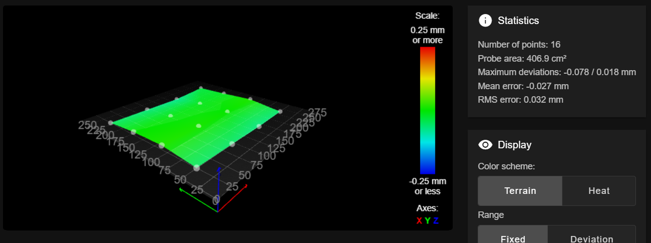
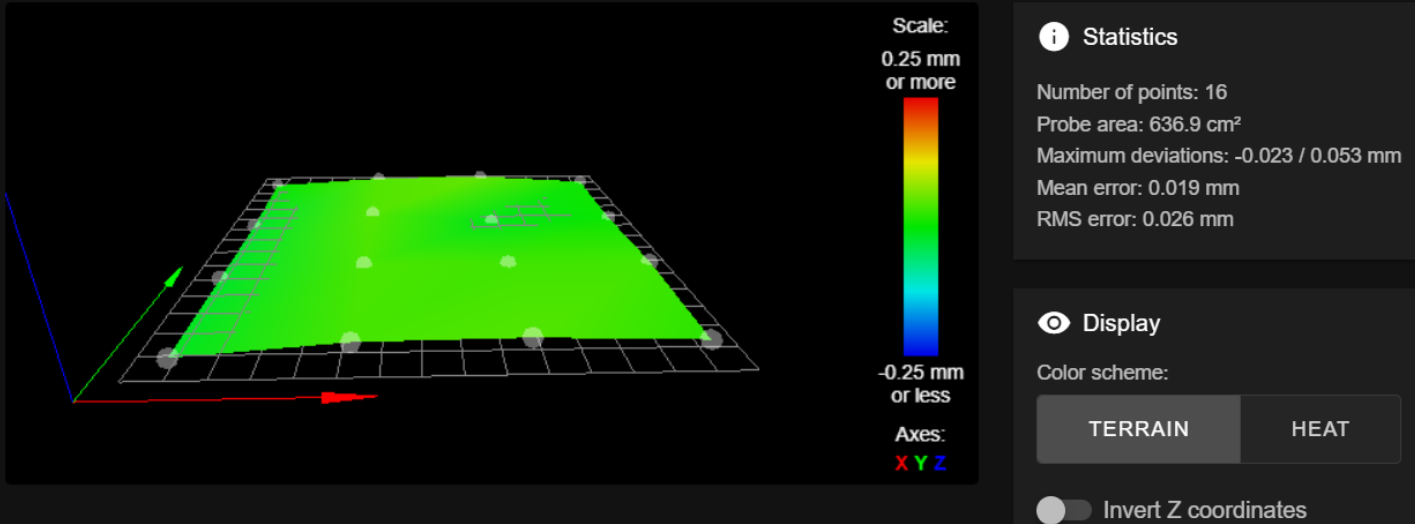
@fcwilt My first post has all the data. I just ran G32 again and this is the result.
Leadscrew adjustments made: 0.048 0.048 0.060, points used 3, (mean, deviation) before (0.052, 0.006) after (-0.000, 0.000)
16 points probed, min error -0.080, max error 0.108, mean 0.023, deviation 0.050
Height map saved to file 0:/sys/heightmap.csv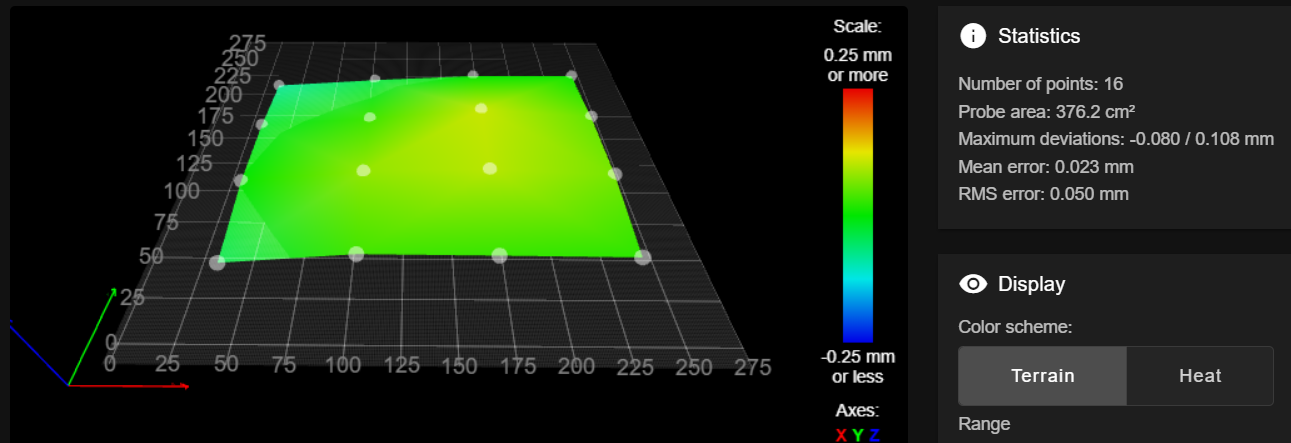
-
@stephen6309 said in Euclid probe and Z=0 datum:
G30 S-2 sets Z0 where the probe triggered. Probes don't trigger the same distance when the nozzle hits the bed, unless the hotend triggers the probe.
S-2 sets the Z offset of the current tool. There is no reason to do that when there is only one tool as the relationship of the tool to the nozzle is fixed.
G30 alone sets the Z axis position to whatever the Z probe Z Trigger Height parameter is. This is intended to insure the Z=0 position of the tip of the nozzle is correct. If the Z Trigger Height parameter is wrong then Z=0 will be off.
Frederick
-
@dhusolo said in Euclid probe and Z=0 datum:
@fcwilt My first post has all the data. I just ran G32 again and this is the result.
Leadscrew adjustments made: 0.048 0.048 0.060, points used 3, (mean, deviation) before (0.052, 0.006) after (-0.000, 0.000)
16 points probed, min error -0.080, max error 0.108, mean 0.023, deviation 0.050
Height map saved to file 0:/sys/heightmap.csv
Aside from not using very many points that heightmap looks OK.
Are you using the left, front grid point to set the Z=0 Datum?
Frederick
-
@fcwilt No I use bed center for Z=0 Datum. That's the way I've always done it.
-
@dhusolo said in Euclid probe and Z=0 datum:
@fcwilt No I use bed center for Z=0 Datum. That's the way I've always done it.
That's fine - that is what I do.
Try specifying a 3x3 grid or a 5x5 grid. The goal is to have the XY position of the center grid point match the XY position used for setting the Z=0 Datum.
If all is good the center most point should be reported as 0 deviation.
Frederick
-
@fcwilt I went with a 5x5 grid and this is the result
Leadscrew adjustments made: -0.197 -0.156 -0.063, points used 3, (mean, deviation) before (-0.142, 0.055) after (0.000, 0.000)
Warning: the height map has a substantial Z offset. Suggest use Z-probe to establish Z=0 datum, then re-probe the mesh.
25 points probed, min error -0.242, max error -0.005, mean -0.139, deviation 0.059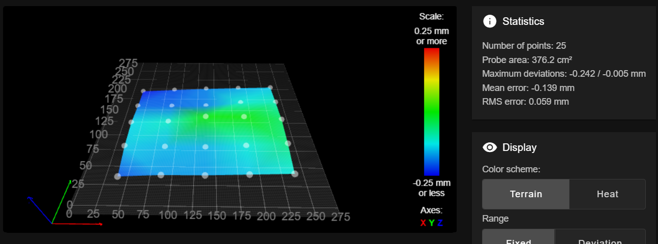
-
Did you determine the XY position of the center point of the grid and use that as the probe XY position when doing the G30 before creating the height map?
Remember when setting the XY position of the probe you have to take into account the XY offsets of the probe.
Frederick
-
@dhusolo Did you get this sorted out ?
-
I usually recommend that the Z point be taken at the geometric center of the 3 kinematic mounts or Z-screws. that point should not really move- everything tips through this point.
-
I seem to get better results with 4 point bedleveling than with 3, that is why the example macros are with 4.
-
Verify that your Z probe trigger point is right. That might throw you off too. Lots of ways to measure this, but I will hold off on your reply.
-
Rememer that sag in the gantry will show up in the terrain map as high points. Its hard to say from the screens shots, but your X rails might be a hair out. You should decide if its worth fussing with.
The folks here and on the Euclid and RC discord are very helpful. We'll get you sorted.
sinneD
-
-
@sinned6915 When I try 4 it gives me an error stating I'm unable to do 4 point leveling because I have 3 lead screws defined.
I switched back to a super pinda. and the mesh looks similar to the last one I posted 2 days ago. I'm going to take a step back and look at the frame and motion mechanics. I think something else might be contributing to this or my bed is really that bed.
-
@dhusolo I only have 3 leadscrews also. I probe 4 points that are symmetric in proportion to the shape of my bed.
This is the code I currently run :
; *********************************************************** ; bed4point.g ; *********************************************************** ; probe is -16.4 in X -29.4 in Y bed is 290 in X 325 in Y ; adjust coords so that probe hits symmetric points on bed and avoids dock ; echo move.axes[2].machinePosition ; echo "Running bed4point.g" G90 G30 X145 Y145.0 F600.0 ; home Z G30 P0 X17.0 Y30.0 F9000.0 Z-99999 ; probe front left PEI G30 P1 X17.0 Y265.0 F9000.0 Z-99999 ; probe back left PEI G30 P2 X278.0 Y265.0 F9000.0 Z-99999 ; probe back right PEI G30 P3 X278.0 Y30.0 F9000.0 Z-99999 S3 ; probe near front right leadscrew and calibrate 3 motors PEI ; echo "bed4point.g complete" -
@sinned6915 Ah ok i see what I did wrong. You have 4 G30 coordinates to probe but you still use S3 to define you have 3 leadscrews.
-
@dhusolo glad that helped.
whenever you decide to go back to Euclid, we are here for your if yo need help.
I think you will be well served by both the SuperPinda and the Euclid. -
@sinned6915 Ok so I think the problem was my lead screws. My teflon coated lead screws arrived today and it's more manageable.
Railcore 250zl bed
Granted not as good as my printer with the Railcore 300zl bed and Super Pinda
but it's better than what it was. -
One nice thing about the Euclid is that it uses a simple microswitch - which are perhaps the most accurate of all Z probe designs.
And while the Super Pinda is nice, being temp compensated, it requires a probing speed a good deal slower than a microswitch.
I haven't found the specified switching frequency of the Super Pinda. The switching frequency of a capacitive or inductive probe is a primary factor in how fast you can probe. Some capacitive probes have a switching frequency as low as 50 Hz. Top quality inductive probes will have a switching frequency as high as 3000 Hz or better.
Frederick
Printers: a small Utilmaker style, a small CoreXY and a E3D MS/TC setup. Various hotends. Using Duet 3 hardware running 3.4.6
-
but it's better than what it was.
i would be tempted to take that and call it a day! the amount of effort to reduce that could be a lot to futzing time. -
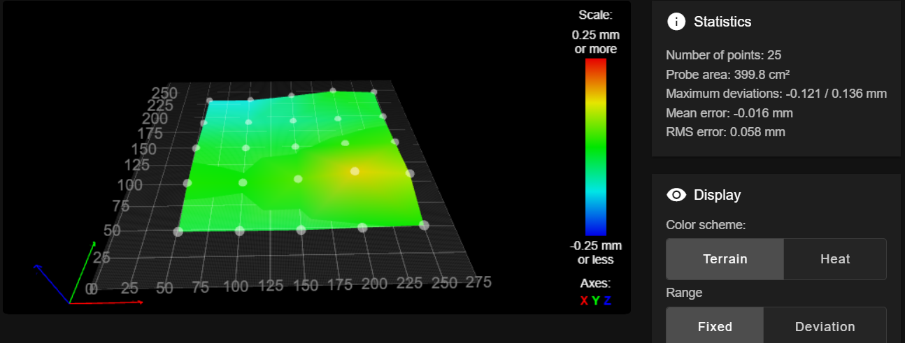
@fcwilt Agreed. I planned to incorporate it in my build and was disappointed when I couldn't use it. However after enough tweaking I think I'm in a better place. Upgrading to the PTFE coated leadscrews helped quite a bit. I also figured out the leadscrew offsets were slightly off. Once I changed the config results started to improve. Even more so after using 4 points to calculate the leadscrew offset. This was my last G32 without the spring steel sheet on.