error G0\G1 home Z ratrig vcore 500
-
Where do you have the BLTouch wires connected? Can you show a photo? Did you delete the inductive probe lines?
-
@Phaedrux
I checked BLTouch wirring twice.
Yes, I delete two command inductive probe

-
@dejvid17 Those wires look to big for the connector really but if it's a solid connection and you have no loose wire strands that can short out it's "ok" for now I guess.
But your current issue is that you need to look at the duet mini 5+ pinout and adjust your config.g.
I.e there isn't a io7 on a mini5+. https://docs.duet3d.com/Duet3D_hardware/Duet_3_family/Duet_3_Mini_5+_Hardware_Overview
-
@rushmere3d thank you !! I change 7 for 2 and home Z done..
but now I tried to bed leveling and another error
G32
Error: Some computed corrections exceed configured limit of 5.00mm: -500.000 -500.000 -500.000 -
@dejvid17 was the bed in the position you posted earlier? I think it's referring to the S5 in your M671, the correction is more than 5mm.
-
@rushmere3d yes, but next time I correct manual level of the bed and again the same error
M671
Z leadscrew coordinates (-4.5,-4.5) (250.0,505.0) (504.5,-4.5), factor 1.00, maximum correction 5.00mm, manual adjusting screw pitch 0.50mmwhen I change Z from -500 to 500 error almost the same G32
Error: Some computed corrections exceed configured limit of 5.00mm: 500.000 500.000 500.000bed.g
; this script compensates for what the Z offset is
; so if G31 P500 X-30 Y-15 Z1.7 then first probe will be at
; X30 Y20 (when G30 P0 X0 Y5)M561 ; clear any bed transform
G30 P0 X5 Y5 Z500 ; probe near a leadscrew
G30 P1 X150 Y285 Z500 ; probe near a leadscrew
G30 P2 X270 Y5 Z500 S3 ; probe near a leadscrew and calibrate 3 motors -
@dejvid17 Not sure on that one, it feels like it's to do with the whole file set and coordinates. Like can the lead screw coordinates be greater than the min/max? Someone else will need to chip in on it.
-
@dejvid17 said in error G0\G1 home Z ratrig vcore 500:
G30 P0 X5 Y5 Z500 ; probe near a leadscrew
G30 P1 X150 Y285 Z500 ; probe near a leadscrew
G30 P2 X270 Y5 Z500 S3 ; probe near a leadscrew and calibrate 3 motorsI think you need to remove the Z500 from those lines.
-
@phaedrux thank you
Z should be 99999 and everything works fine.. -
 undefined Phaedrux marked this topic as a question
-
 undefined Phaedrux has marked this topic as solved
-
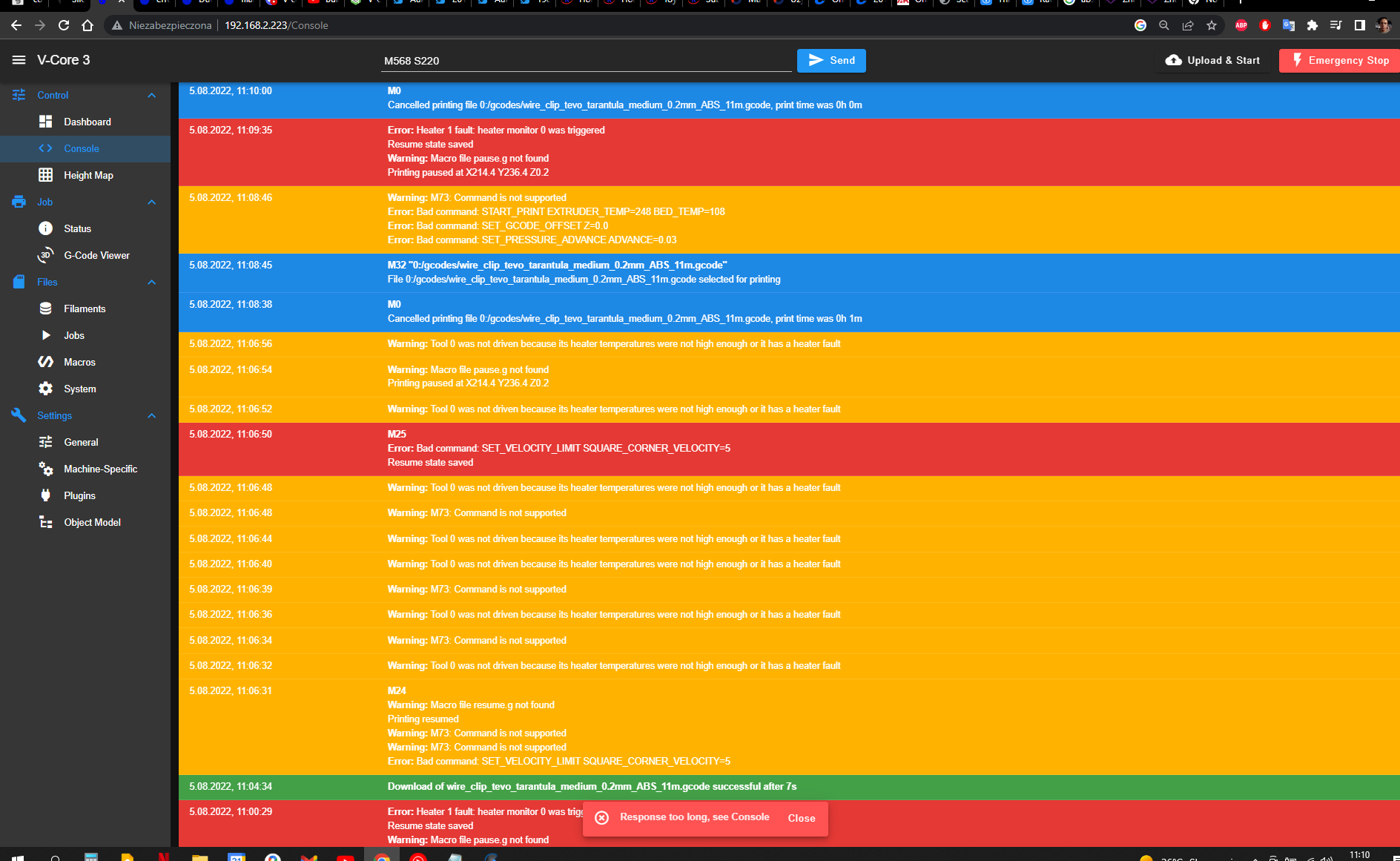
Guy's any ideas what this time is wrong????
-
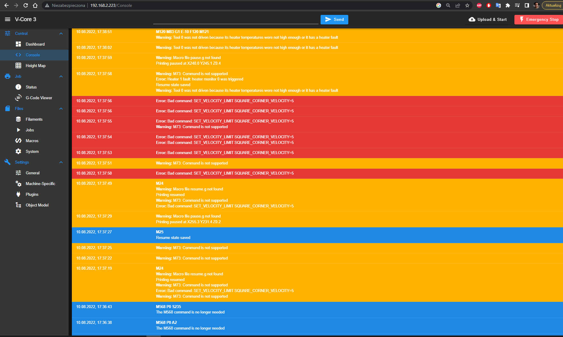
It's telling you a lot of the issues, files not found and bad commands.
You seems to be sending Klipper commands?
Do you have a Pause. and Resume.g?
-
@rushmere3d
I send from super slicer project to printer and after a few sec first error heater 1 no pause.g fileno any of those files
-
@dejvid17
What firmware is superslicer set up for?
Whats in your Start and end gcode boxes? -
@Rushmere3D
Super slicer fixed up in setting printer was Klipper.
but I don;'t know what do with thatError: Heater 1 fault: heater monitor 0 was triggered Error: Heater 0 fault: temperature rising much more slowly than the expected 1.7°C/secError: Can't activate heater 0 while in fault state
Resume state saved
Warning: Macro file pause.g not foundconfig.g
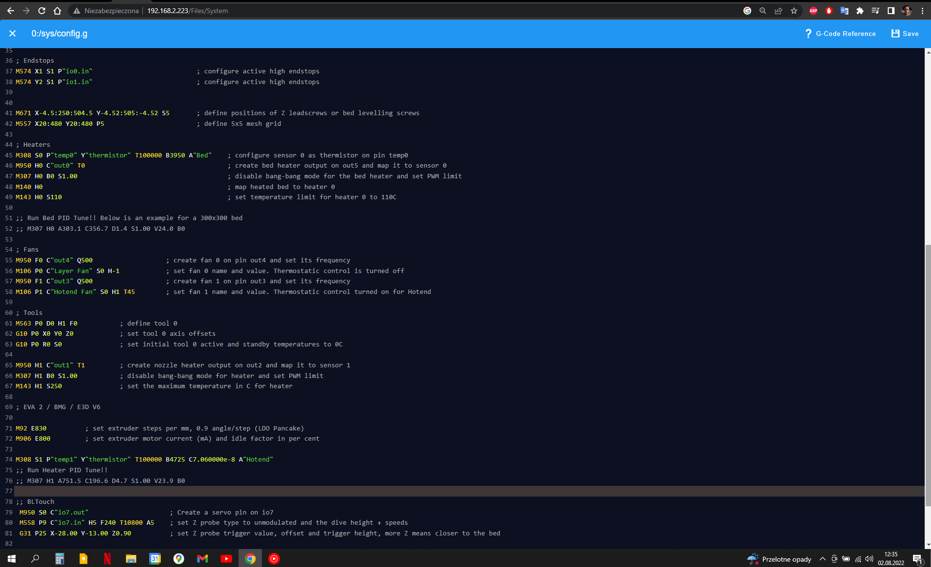
; Heaters
M308 S0 P"temp0" Y"thermistor" T100000 B3950 A"Bed" ; configure sensor 0 as thermistor on pin temp0
M950 H0 C"out0" T0 ; create bed heater output on out5 and map it to sensor 0
M307 H0 A303.1 C356.7 D1.4 S1.00 V24.0 B0 ; disable bang-bang mode for the bed heater and set PWM limit
M140 H0 ; map heated bed to heater 0
M143 H0 S110 ; set temperature limit for heater 0 to 110C;; Run Bed PID Tune!! Below is an example for a 300x300 bed
;; M307 H0 A303.1 C356.7 D1.4 S1.00 V24.0 B0; Fans
M950 F0 C"out4" Q500 ; create fan 0 on pin out4 and set its frequency
M106 P0 C"Layer Fan" S0 H-1 ; set fan 0 name and value. Thermostatic control is turned off
M950 F1 C"out3" Q500 ; create fan 1 on pin out3 and set its frequency
M106 P1 C"Hotend Fan" S0 H1 T45 ; set fan 1 name and value. Thermostatic control turned on for Hotend; Tools
M563 P0 D0 H1 F0 ; define tool 0
G10 P0 X0 Y0 Z0 ; set tool 0 axis offsets
G10 P0 R0 S0 ; set initial tool 0 active and standby temperatures to 0CM950 H1 C"out1" T1 ; create nozzle heater output on out2 and map it to sensor 1
M307 H1 B0 S1.00 ; disable bang-bang mode for heater and set PWM limit
M143 H1 S250 ; set the maximum temperature in C for heater; EVA 2 / BMG / E3D V6
M92 E830 ; set extruder steps per mm, 0.9 angle/step (LDO Pancake)
M906 E800 ; set extruder motor current (mA) and idle factor in per centM308 S1 P"temp1" Y"thermistor" T100000 B4725 C7.060000e-8 A"Hotend"
;; Run Heater PID Tune!!
;; M307 H1 A751.5 C196.6 D4.7 S1.00 V23.9 B0 -
@dejvid17 Have you PID tuned both the bed and hotend?
-
@rushmere3d Yes both
and still the same problem Error: Heater 0 fault: temperature rising much more slowly than the expected 0.6°C/sec -
-
I don't know what to do now...
I can't manual set temperature of the hotend only command M303 H1 S works and when I tried to print something super slicer set hotend 248 degrees but after minute againg error about rising temp too slow; Endstops
M574 X1 S1 P"io0.in" ; configure active high endstops
M574 Y2 S1 P"io1.in" ; configure active high endstopsM671 X-4.5:250:504.5 Y-4.52:505:-4.52 S5 ; define positions of Z leadscrews or bed levelling screws
M557 X20:480 Y20:480 P5 ; define 5x5 mesh grid; Heaters
M308 S0 P"temp0" Y"thermistor" T100000 B3950 A"Bed" ; configure sensor 0 as thermistor on pin temp0
M950 H0 C"out0" T0 ; create bed heater output on out5 and map it to sensor 0
M307 H1 R2.794 C222.6 D8.63 S1.00 V24.2 ; disable bang-bang mode for the bed heater and set PWM limit
M140 H0 ; map heated bed to heater 0
M143 H0 S110 ; set temperature limit for heater 0 to 110C;; Run Bed PID Tune!! Below is an example for a 300x300 bed
M307 H0 A303.1 C356.7 D1.4 S1.00 V24.0 B0; Fans
M950 F0 C"out4" Q500 ; create fan 0 on pin out4 and set its frequency
M106 P0 C"Layer Fan" S0 H-1 ; set fan 0 name and value. Thermostatic control is turned off
M950 F1 C"out3" Q500 ; create fan 1 on pin out3 and set its frequency
M106 P1 C"Hotend Fan" S0 H1 T45 ; set fan 1 name and value. Thermostatic control turned on for Hotend; Tools
M563 P0 D0 H1 F0 ; define tool 0
G10 P0 X0 Y0 Z0 ; set tool 0 axis offsets
G10 P0 R0 S0 ; set initial tool 0 active and standby temperatures to 0CM950 H1 C"out1" T1 ; create nozzle heater output on out2 and map it to sensor 1
M307 H1 B0 S1.00 ; disable bang-bang mode for heater and set PWM limit
M143 H1 S250 ; set the maximum temperature in C for heater; EVA 2 / BMG / E3D V6
M92 E830 ; set extruder steps per mm, 0.9 angle/step (LDO Pancake)
M906 E800 ; set extruder motor current (mA) and idle factor in per centM308 S1 P"temp1" Y"thermistor" T100000 B4725 C7.060000e-8 A"Hotend"
;; Run Heater PID Tune!!
M307 H1 A751.5 C196.6 D4.7 S1.00 V23.9 B0; Z-Probe
;; Inductive Probe
M558 P5 C"!io3.in" H5 F400 T5000 ; set Z probe type to unmodulated and the dive height + speeds
G31 P500 X-30 Y-15 Z0.20 ; set Z probe trigger value, offset and trigger height, more Z means closer to the bed
; BLTouch
M950 S0 C"io2.out" ; Create a servo pin on io7
M558 P9 C"io2.in" H5 F240 T10800 A5 ; set Z probe type to unmodulated and the dive height + speeds
G31 P25 X-28.00 Y-13.00 Z0.90 ; set Z probe trigger value, offset and trigger height, more Z means closer to the bed; Select default tool
T0; Pressure Advance
M572 D0 S0.10 -
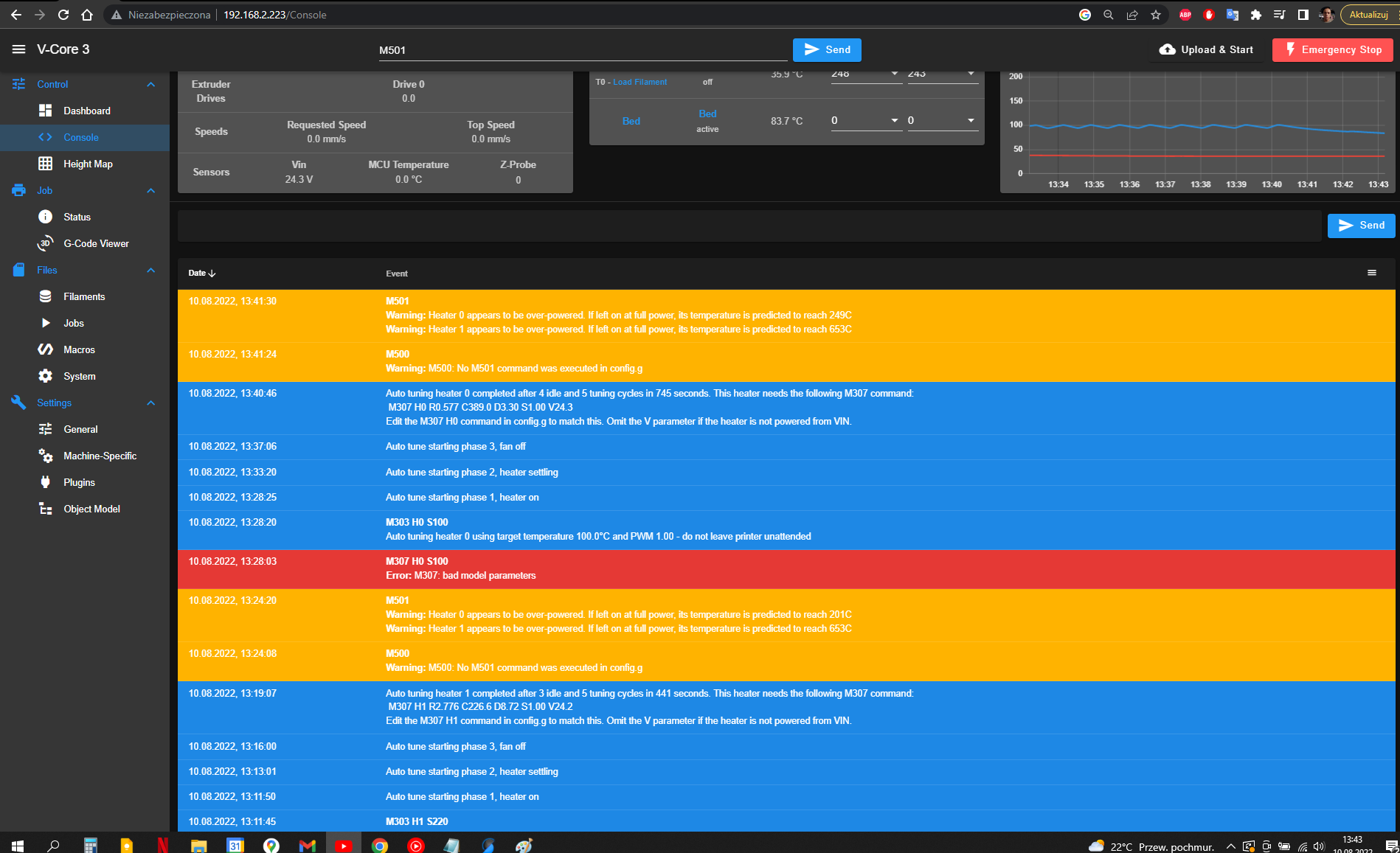
@dejvid17 after tuning heaters you have used M500 to save the new M307 parameters to config-ovwrride.g, but you don;t have a M501 command in config.g to read config-override.g at startup. That's why RRF told you to edit the M307 commands in config.g to match the values obtained by tuning. Did you do that?
-
@dc42
I know I'm annoing butError: Heater 1 fault: heater monitor 0 was triggered
Resume state saved
Warning: Macro file pause.g not found
Printing paused at X250.0 Y250.0 Z10.9M32 "0:/gcodes/1111111.gcode"
File 0:/gcodes/1111111.gcode selected for printing
Warning: M73: Command is not supported
Error: Bad command: START_PRINT EXTRUDER_TEMP=248 BED_TEMP=108
Error: Bad command: SET_GCODE_OFFSET Z=0.0
Error: Bad command: SET_PRESSURE_ADVANCE ADVANCE=0.03config-override.g
; config-override.g file generated in response to M500 at 2022-08-10 16:57
; This is a system-generated file - do not edit
; Heater model parameters
M307 H0 R0.582 C398.938:398.938 D3.39 S1.00 V24.3 B0
M307 H1 R2.788 C216.240:216.240 D8.68 S1.00 V24.2 B0
; Workplace coordinates
G10 L2 P1 X0.00 Y0.00 Z0.00
G10 L2 P2 X0.00 Y0.00 Z0.00
G10 L2 P3 X0.00 Y0.00 Z0.00
G10 L2 P4 X0.00 Y0.00 Z0.00
G10 L2 P5 X0.00 Y0.00 Z0.00
G10 L2 P6 X0.00 Y0.00 Z0.00
G10 L2 P7 X0.00 Y0.00 Z0.00
G10 L2 P8 X0.00 Y0.00 Z0.00
G10 L2 P9 X0.00 Y0.00 Z0.00
M486 S-1I add command M501 on the end of config.g


