Mistake True bed levelling G32
-
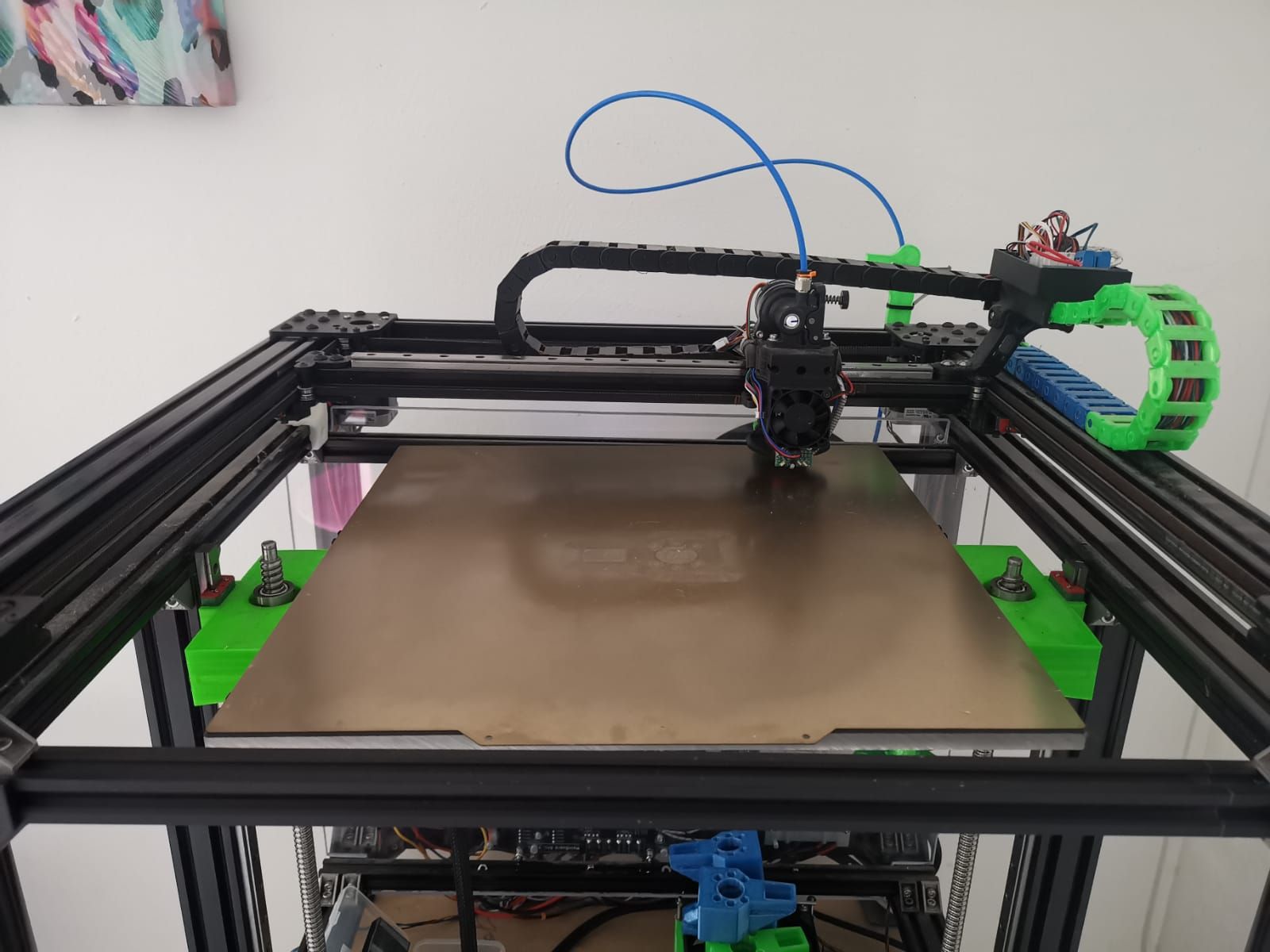
hello friends after installing my duet 3 6hc card I have a size problem every time I do G32 the bed goes down each time on the left side and it is not level while it shows me that yes like we see it on this command after the g32.
Leadscrew adjustments made: -1.495 1.607, points used 2, (mean, deviation) before (0.136, 1.213) after (-0.000, 0.000).
anyone have an idea please.
-
@sgk post your current config and your bed.g file.
Also, some info about where your probe is etc -
@jay_s_uk
hello Jay thank you for answering me.
bed.g config (4).g homez (1).g
prob ir 42 -
@sgk files for other peoples reference
; Configuration file for Duet 3 (firmware version 3)
; executed by the firmware on start-up
;
; generated by Ben Levi - BLV developer as a basic version

; ================ General preferences ============
G90                                                ; send absolute coordinates...
M83                                                ; ...but relative extruder moves
M550 P"duet3-sgk008"                                   ; set printer name
M669 K1                                            ; select CoreXY mode

; ================ Network ========================
M552 S1                                   ; enable network and acquire dynamic address via DHCP
M586 P0 S1                                         ; enable HTTP
M586 P1 S0                                         ; disable FTP
M586 P2 S0                                         ; disable Telnet

; ================ Drives mapping =================

M569 P1 S0                                       ; physical drive 0.1 goes forwards - X driver
M569 P2 S0                                       ; physical drive 0.2 goes forwards - Y driver
M569 P3 S1                                       ; physical drive 0.3 goes forwards - Z1 Right driver
M569 P4 S0                                       ; physical drive 0.4 goes forwards - Z2 Left driver
M569 P0 S1                                       ; physical drive 0.0 goes forwards - extruder driver
M584 X1 Y2 Z3:4 E0                               ; set drive mapping


; ================ Drives settings ================
M350 X16 Y16 Z16 E16 I1                            ; configure microstepping with interpolation
M92 X200.00 Y200.00 Z800.00 E917.444               ; set steps per mm - for Matrix extruder:E324.214
;M566 X700.00 Y700.00 Z24.00 E2000.00               ; set maximum instantaneous speed changes (mm/min)
;M203 X35000.00 Y35000.00 Z1200.00 E5000.00         ; set maximum speeds (mm/min)
M566 X500 Y500 Z800 E600                          ; Set maximum instantaneous speed changes (Jerk) (mm/min)
M203 X20000 Y20000 Z600 E3600                      ; Set maximum speeds (mm/min)
;M201 X6000.00 Y6000.00 Z400.00 E2500.00            ; set accelerations (mm/s^2)
M201 X1000 Y1000 Z100 E600 	                   ; Set accelerations (mm/s^2)
;M906 X1600 Y1600 Z1600 E1000 I30              ; set motor currents (mA) and motor idle factor in per cent
M906 X1350 Y1350 Z1200 E700 I10                   ; Set motor currents (mA) and motor idle factor in per cent
M84 S60                                            ; Set idle timeout

; ================ Independent Z leveling (original 2 z-axis) =================
;M671 X369.75:-59.75 Y155:155 S5					   ; Define positions of Z leadscrews for Independent Z leveling
M671 X-45.0:364.0 Y165.0:165.0 S5.0                ;bed compensation

; ================ Axis Limits ====================
;M208 X-35.5 Y0 Z0 S1                                 ; set axis minima
;M208 X320 Y326.8 Z340 S0                             ; set axis maxima
M208 X-3.50 Y0 Z0 S1                                                             ; Set axis minima
M208 X340 Y320 Z350 S0                                                         ; Set axis maxima

; ================ Endstops =======================
M574 X1 S1 P"io0.in"                               ; configure active-high endstop for low end on X via pin io0.in
M574 Y2 S1 P"io1.in"                               ; configure active-high endstop for low end on Y via pin io1.in
M574 Z1 S2                                         ; configure Z-probe endstop for low end on Z

; ================ Z-Probe ========================
M558 P8 C"io2.in" A5 B1 H5 F120 T15000              ; set Z probe type to unmodulated and the dive height + speeds (for Mini IR sensor M558 P8 C"io2.in" A2 H5 F120 T15000)
;G31 P50 X11.5 Y65.8 Z1.035	                   ; set Z probe trigger value, offset and trigger height Z1.023
G31 P50 X-1 Y-20 Z1.300                                 ; Set Z probe trigger  value, offset and trigger height
M556 S50 X0 Y0 Z0                                  ; set orthogonal axis compensation parameters
;M557 X30:270 Y30:270 P4                            ; define mesh grid
M557 X20:270 Y20:270 P3                         ; Define mesh grid


; ================ Heaters ==============================================
M308 S0 P"temp0" Y"thermistor" A"Bed" T100000 B3950       				 ; configure sensor 0 as thermistor on pin temp0
M950 H0 Q10 C"out1" T0                                					 ; create bed heater output on out0 and map it to sensor 0 (if NOT using SSR - delete Q10)
M307 H0 R0.291 K0.269:0.000 D12.75 E1.35 S1.00 B0                              	 ; disable bang-bang mode for the bed heater and set PWM limit
M140 H0                                            						 ; map heated bed to heater 0
M143 H0 S100                                     						 ; set temperature limit for heater 0 to 100C
M308 S1 P"temp1" Y"thermistor" A"Hotend" T107537 B4725 C7.06e-8	 		 ; configure sensor 1 as thermistor on pin temp1
M950 H1 C"out2" T1                                						 ; create nozzle heater output on out1 and map it to sensor 1
M307 H1 R2.438 K0.550:0.123 D5.13 E1.35 S1.00 B0 V24.1       			 ; disable bang-bang mode for heater  and set PWM limit
M143 H1 S280                                       						 ; set temperature limit for heater 1 to 280C

; ================ Fans & Lights ==================
M950 F0 C"out7" Q500 				               ; create fan 0 on pin out7 and set its frequency
M106 P0 S0 H1 T35                                  ; set fan 0 value. Thermostatic control is turned on
M950 F1 C"out8" Q500                               ; create fan 1 on pin out8 and set its frequency
M106 P1 S0 H-1 C"Layers Fan"                       ; set fan 1 value. Thermostatic control is turned off
M950 F2 C"out9" Q500                               ; create fan 2 on pin out9 and set its frequency (lights)
M106 P2 S0.2 H-1 C"Lights"                         ; set fan 2 value. Thermostatic control is turned off (lights)

; ================ Tools ==========================
M563 P0 D0 H1 F1                                 ; define tool 0
G10 P0 X0 Y0 Z0                                    ; set tool 0 axis offsets
G10 P0 R0 S0                                       ; set initial tool 0 active and standby temperatures to 0C

; ================ Miscellaneous ==================
;M575 P1 S1 B57600                                  ; enable support for PanelDue
M911 S10 R11 P"M913 X0 Y0 G91 M83 G1 Z3 E-5 F1000" ; set voltage thresholds and actions to run on power loss
; homez.g ; called to home the Z axis ; ; generated by Ben Levi - BLV developer as a basic version G91 ; relative positioning G1 H2 Z5 F6000 S2 ; lift Z relative to current position G90 ; absolute positioning G1 X152 Y166.4 F6000 ; go to first probe point G30 ; home Z by probing the bed ; Uncomment the following lines to lift Z after probing ;G91 ; relative positioning ;G1 Z5 F100 ; lift Z relative to current position ;G90 ; absolute positioning; bed.g ; called to perform automatic bed compensation via G32 ; ; generated by Ben Levi - BLV developer as a basic version M561 ; clear any bed transform G91 ; relative positioning G1 H2 Z5 F6000 ; lift Z relative to current position G90 ; absolute positioning G28 ; home all M557 X20:270 Y20:270 P3 ; Define mesh grid G30 P1 X10 Y175 Z-99999 ; probe near a leadscrew, half way along Y axis G30 P0 X330 Y175 Z-99999 S2 ; probe near a leadscrew and calibrate 2 motors G29 S0 ; probe the bed and enable compensation M291 P"Leveling finished !" R"Probing.." S1 T2 -
@sgk there doesn't appear to be anything wrong with your config.
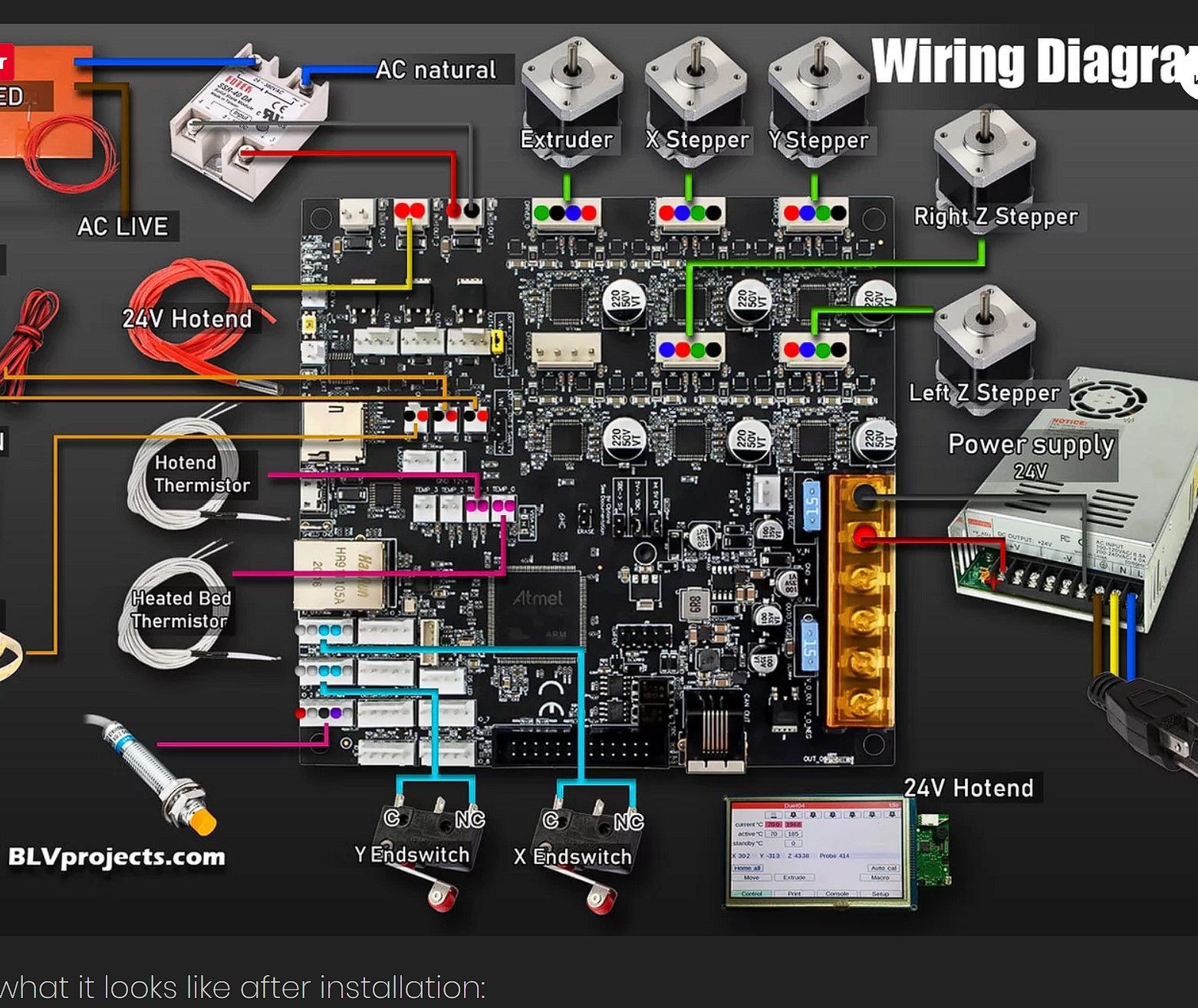
Can you confirm that the stepper motor attached to driver 3 is the one thats X-45 Y165 and that the other stepper motor connected to driver 4 is the one on the other side? -
@jay_s_uk
they are connected as in the photo though
-
@sgk is the left one the one closest to X0?
-
@jay_s_uk excuse me I don't understand questions?
-
@sgk well when the tool is at X0, is it nearest the motor called "left z stepper" or is it closest to the one called "right z stepper"?
-
@jay_s_uk to the left
-
@sgk which indicates that the firmware setup is correct then and its left to either be a mechanical issue, e.g. x axis twist or maybe the IR probe doesn't like being so close to the edge of the bed
-
@jay_s_uk
the impression that I have is that each time I do g32 the bed does not get level and it always goes down more and more on the side -
@jay_s_uk I could make a video to better understand
-
@sgk which is why i think you have the stepper motors the wrong way round
-
@jay_s_uk but when I do home all the 2 z motors go well together they are synchronized
-
@sgk if you have them mapped the wrong way round, RRF will adjust the wrong one
-
@jay_s_uk I could solve this problem how do you have an idea please
-
@sgk change your z mapping in M584 from Z3:4 to Z4:3
-
@jay_s_uk
ha ok i will try now thank -
@jay_s_uk I have this as an error
Error: Z probe readings not consistent