Duet3D Logo Duet3D
    • Tags
    • Documentation
    • Order
    • Register
    • Login

    6XD Out 3 4 5

    Scheduled Pinned Locked Moved
    Using Duet Controllers
    3
    17
    525
    Loading More Posts
    • Oldest to Newest
    • Newest to Oldest
    • Most Votes
    Reply
    • Reply as topic
    Log in to reply
    This topic has been deleted. Only users with topic management privileges can see it.
    • HighFrequndefined
      HighFreq
      last edited by HighFreq

      I am trying to have 12V or 24V (my input) on 6XD pins 3 4 5 but i can't. From my understanding it should be possible but all i get is 3,3V.

      T3P3Tonyundefined A Former User? 2 Replies Last reply Reply Quote 0
      • T3P3Tonyundefined
        T3P3Tony administrators @HighFreq
        last edited by

        @highfreq please share how you are connecting things, do you mean on OUT3,4,5 or something else? if OUT3,4,5 then how is the jumper for the voltage select set?

        www.duet3d.com

        HighFrequndefined 1 Reply Last reply Reply Quote 0
        • A Former User?
          A Former User @HighFreq
          last edited by A Former User

          This post is deleted!
          T3P3Tonyundefined 1 Reply Last reply Reply Quote 0
          • HighFrequndefined
            HighFreq @T3P3Tony
            last edited by

            @t3p3tony

            Yes Out 3 4 5
            Jumper is toward the side of the board where it says "VIN". I guess it should output my 24V IN voltage.

            1 Reply Last reply Reply Quote 0
            • T3P3Tonyundefined
              T3P3Tony administrators @A Former User
              last edited by

              @herve_smith said in 6XD Out 3 4 5:

              The jumpers on the silkscreen say " V Out 3-5" on the left most jumper but the diagram lists it as "out 4-6" which conflicts with the silkscreen

              Thanks for pointing this out. I have just fixed the labelling issue with the wiring diagram.

              @HighFreq yes if its towards the VIN it will connect VIN to V_OUTLC1 on those headers

              Where are you measuring 3.3V? possibly the tacho pins?

              www.duet3d.com

              HighFrequndefined 1 Reply Last reply Reply Quote 0
              • HighFrequndefined
                HighFreq @T3P3Tony
                last edited by HighFreq

                @t3p3tony between ground and lc_out (first and third pin from down).
                Same with gound and vout, first and fourth pin.

                None of them outputs 24V (my Vin).

                T3P3Tonyundefined 1 Reply Last reply Reply Quote 0
                • T3P3Tonyundefined
                  T3P3Tony administrators @HighFreq
                  last edited by

                  @highfreq the way you describe the pins does not fit with the wiring diagram (depending which way we describe as up and down.)

                  86da46dc-2a3b-4551-b15f-7c8a5221555a-image.png

                  www.duet3d.com

                  HighFrequndefined 1 Reply Last reply Reply Quote 0
                  • HighFrequndefined
                    HighFreq @T3P3Tony
                    last edited by HighFreq

                    @t3p3tony counting from the bottm, first is ground. So i expect 24V (my Vin) between ground (firt from bottom) and third or fourth pin. Correct?
                    Neither V_OUTLC1 or out5- put out 24 Volts. All i get is 3.3V
                    Where should i get 24V?
                    I tried between out5 and v_outlc1 too and i get 0 and 3.3V

                    T3P3Tonyundefined 1 Reply Last reply Reply Quote 0
                    • T3P3Tonyundefined
                      T3P3Tony administrators @HighFreq
                      last edited by

                      @highfreq 24V should be on V_OUTLC1. Test on your input terminals and the jumper as well, maybe there is an issue with the jumper.

                      www.duet3d.com

                      HighFrequndefined 1 Reply Last reply Reply Quote 0
                      • HighFrequndefined
                        HighFreq @T3P3Tony
                        last edited by

                        @t3p3tony Should be between V_OUTLC1 and ground or between V_OUTLC1 and out5?

                        T3P3Tonyundefined 1 Reply Last reply Reply Quote 0
                        • T3P3Tonyundefined
                          T3P3Tony administrators @HighFreq
                          last edited by

                          @highfreq

                          V_OUTLC1 and GND. Also between V_OUTLC1 and out5- when out5- is turned on.

                          www.duet3d.com

                          HighFrequndefined 1 Reply Last reply Reply Quote 0
                          • HighFrequndefined
                            HighFreq @T3P3Tony
                            last edited by HighFreq

                            @t3p3tony i only get 0 or 3.3V between V_OUTLC1 and out5.
                            0 when off ad 3.3V when on.
                            Do you have a chance to test to see if there is a problem on the 6XD?

                            T3P3Tonyundefined 1 Reply Last reply Reply Quote 0
                            • T3P3Tonyundefined
                              T3P3Tony administrators @HighFreq
                              last edited by T3P3Tony

                              @highfreq please test between ground and VIN on the input terminal and between ground and the center pin of the 3 pin jumper It may be that the fuse has blown

                              www.duet3d.com

                              HighFrequndefined 2 Replies Last reply Reply Quote 0
                              • HighFrequndefined
                                HighFreq @T3P3Tony
                                last edited by

                                @t3p3tony will test tomorrow as soon as i get in office, thanks for your help.

                                1 Reply Last reply Reply Quote 0
                                • HighFrequndefined
                                  HighFreq @T3P3Tony
                                  last edited by HighFreq

                                  @t3p3tony Fuse is ok, can you please check if there is an error on the board?
                                  The OUTLC2 works at 25V as expected, while OUTLC1 is at 3.3V.

                                  I think there is some error on the board between the jumper and the OUTLC1.

                                  It works if i use out5.tach so i guess pin V_OUTLC1 and out5.tach are inverted.

                                  There is 25 Volts on out5.tach instead of V_OUTLC1.

                                  Please let me know.

                                  T3P3Tonyundefined 1 Reply Last reply Reply Quote 0
                                  • T3P3Tonyundefined
                                    T3P3Tony administrators @HighFreq
                                    last edited by

                                    @highfreq Ahh right, now I understand what the issue is. Apologies it took so long: the wiring diagram had an error in it, I have fixed that now:
                                    a4eb7cd6-342f-4e83-b205-3ef5fe30a838-image.png

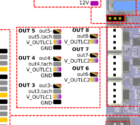
                                    Thanks for your patience and for bearing with me in working out what was wrong.

                                    www.duet3d.com

                                    HighFrequndefined 1 Reply Last reply Reply Quote 0
                                    • HighFrequndefined
                                      HighFreq @T3P3Tony
                                      last edited by

                                      @t3p3tony Ok great, thanks.

                                      Corrado

                                      1 Reply Last reply Reply Quote 0
                                      • First post
                                        Last post
                                      Unless otherwise noted, all forum content is licensed under CC-BY-SA