Duet3D Logo Duet3D
    • Tags
    • Documentation
    • Order
    • Register
    • Login

    Ender 3 mesh grid offset

    Scheduled Pinned Locked Moved
    General Discussion
    3
    24
    940
    Loading More Posts
    • Oldest to Newest
    • Newest to Oldest
    • Most Votes
    Reply
    • Reply as topic
    Log in to reply
    This topic has been deleted. Only users with topic management privileges can see it.
    • re_tourundefined
      re_tour
      last edited by

      Hey guys, I just want to check if I do everything correctly, can someone double check if my mesh grid coordinates are correct?

      ; Configuration file for SKR-RFF-E3-v1.1 (firmware version 3)
      ; executed by the firmware on start-up
      ;
      ; generated by RepRapFirmware Configuration Tool v3.3.1-LPC-STM32+2 on Tue Dec 28 2021 01:07:55 GMT+0100 (közép-európai téli idő)
      
      ; General preferences
      G90                                            ; send absolute coordinates...
      M83                                            ; ...but relative extruder moves
      M550 P"Ender3"                                 ; set printer name
      
      ; Network
      M552 S1                                        ; enable network
      M586 P0 S1                                     ; enable HTTP
      M586 P1 S0                                     ; disable FTP
      M586 P2 S0                                     ; disable Telnet
      
      ; Drives
      M569 P0 S0                                     ; physical drive 0 goes backwards using TMC2209 driver timings
      M569 P1 S0                                     ; physical drive 1 goes backwards using TMC2209 driver timings
      M569 P2 S1                                     ; physical drive 2 goes forwards using TMC2209 driver timings
      M569 P3 S0                                     ; physical drive 3 goes forwards using TMC2209 driver timings
      M584 X0 Y1 Z2 E3                               ; set drive mapping
      M350 X16 Y16 Z16 E16 I1                        ; configure microstepping with interpolation
      M92 X80.00 Y80.00 Z400.00 E93.00               ; set steps per mm
      M566 X1200.00 Y1200.00 Z60.00 E360.00          ; set maximum instantaneous speed changes (mm/min)
      M203 X9000.00 Y9000.00 Z1800.00 E6000.00       ; set maximum speeds (mm/min)
      M201 X500.00 Y500.00 Z100.00 E5000.00          ; set accelerations (mm/s^2)
      M906 X1000 Y1000 Z1000 E1000 I30               ; set motor currents (mA) and motor idle factor in per cent
      M84 S30                                        ; Set idle timeout
      
      ; Axis Limits
      M208 X0 Y0 Z0 S1                               ; set axis minima
      M208 X235 Y235 Z260 S0                         ; set axis maxima
      
      ; Endstops
      M574 X1 S1 P"xstop"                            ; configure switch-type (e.g. microswitch) endstop for low end on X via pin xstop
      M574 Y1 S1 P"ystop"                            ; configure switch-type (e.g. microswitch) endstop for low end on Y via pin ystop
      
      ; Z-Probe
      M950 S0 C"servo0"                              ; create servo pin 0 for BLTouch
      M558 P9 C"^probe" H5 F300:120 A3 T6000         ; set Z probe type to bltouch and the dive height + speeds,the F300:120 first speed 300 second 120
      G31 P500 X0 Y-47 Z2.15                           ; set Z probe trigger value, offset and trigger height
      M557 X30:190 Y30:190 S10                       ; define mesh grid
      
      ; Heaters
      M308 S0 P"bedtemp" Y"thermistor" T100000 B4092 ; configure sensor 0 as thermistor on pin bedtemp
      M950 H0 C"bed" T0                              ; create bed heater output on bed and map it to sensor 0
      M307 H0 B0 R0.365 C296.6 D3.97 S1.00 V24.0                               ; disable bang-bang mode for the bed heater and set PWM limit
      M140 H0                                        ; map heated bed to heater 0
      M143 H0 S120                                   ; set temperature limit for heater 0 to 120C
      M143 H0 S120                                   ; set temperature limit for heater 0 to 120C
      M308 S1 P"e0temp" Y"thermistor" T100000 B4092  ; configure sensor 1 as thermistor on pin e0temp
      M950 H1 C"e0heat" T1                           ; create nozzle heater output on e0heat and map it to sensor 1
      M307 H1 B0 R2.845 C121.4:119.4 D5.71 S1.00 V24.0                               ; disable bang-bang mode for heater  and set PWM limit
      M143 H1 S245                                   ; set temperature limit for heater 1 to 245C
      
      ; Fans
      M950 F0 C"fan0" Q500                           ; create fan 0 on pin fan0 and set its frequency
      M106 P0 C"Part Cooling Fan" S0 H-1             ; set fan 0 name and value. Thermostatic control is turned off
      M950 F1 C"fan1" Q500                           ; create fan 1 on pin fan1 and set its frequency
      M106 P1 C"Hotend Fan" S0.01 H1 T45             ; set fan 1 name and value. Thermostatic control is turned on
      
      ; Tools
      M563 P0 D0 H1 F0                               ; define tool 0
      G10 P0 X0 Y0 Z0                                ; set tool 0 axis offsets
      G10 P0 R0 S0                                   ; set initial tool 0 active and standby temperatures to 0C
      
      ; Custom settings are not defined
      
      M918 P1 E4 E1000000
      

      Creality Ender 3 | BIGTREETECH E3 RRF V1.1 Wifi | BLTouch | RepRap 3.3.0_11

      jay_s_ukundefined 1 Reply Last reply Reply Quote 0
      • jay_s_ukundefined
        jay_s_uk @re_tour
        last edited by

        @re_tour theres no need to offset the mesh in X if you probe X offset is 0. You can probe something like X10 to X225
        Your Y offset can start at 0 as the probe is in front of the nozzle, but you can't have the last row at 190 as the nozzle would have to be at Y237 for the probe to be at Y190 and Y237 is outside the limits set in M208. Change it to something like Y180 or Y185

        Owns various duet boards and is the main wiki maintainer for the Teamgloomy LPC/STM32 port of RRF. Assume I'm running whatever the latest beta/stable build is

        re_tourundefined 2 Replies Last reply Reply Quote 1
        • re_tourundefined
          re_tour @jay_s_uk
          last edited by re_tour

          @jay_s_uk Thank you, I'll give it a go in a moment.

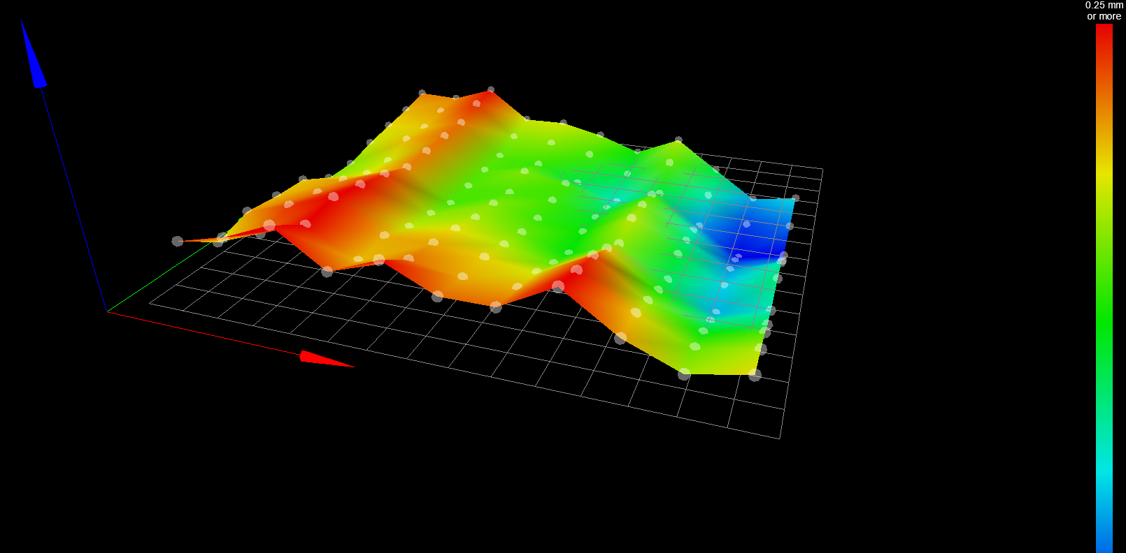
          The other thing is that after I do a mesh compensation the grid map is all wobbly which I don't understand and don't know what to do with it. I'll back this up with an image in a few minutes.

          Creality Ender 3 | BIGTREETECH E3 RRF V1.1 Wifi | BLTouch | RepRap 3.3.0_11

          1 Reply Last reply Reply Quote 0
          • re_tourundefined
            re_tour @jay_s_uk
            last edited by re_tour

            @jay_s_uk c24f75e0-655d-4c69-8f94-eae99d6d295f-kép.png

            This is it, what am I doing wrong?

            Creality Ender 3 | BIGTREETECH E3 RRF V1.1 Wifi | BLTouch | RepRap 3.3.0_11

            jay_s_ukundefined 1 Reply Last reply Reply Quote 0
            • jay_s_ukundefined
              jay_s_uk @re_tour
              last edited by

              @re_tour looks like you may have some movement in your toolhead which may be tilting your probe slightly beween points

              Owns various duet boards and is the main wiki maintainer for the Teamgloomy LPC/STM32 port of RRF. Assume I'm running whatever the latest beta/stable build is

              re_tourundefined 1 Reply Last reply Reply Quote 0
              • re_tourundefined
                re_tour @jay_s_uk
                last edited by

                @jay_s_uk Interesting, how could I test that? I tried moving my tool head but its rock solid, bltouch also has no movement at all, not even bending.

                Creality Ender 3 | BIGTREETECH E3 RRF V1.1 Wifi | BLTouch | RepRap 3.3.0_11

                jay_s_ukundefined 1 Reply Last reply Reply Quote 0
                • jay_s_ukundefined
                  jay_s_uk @re_tour
                  last edited by

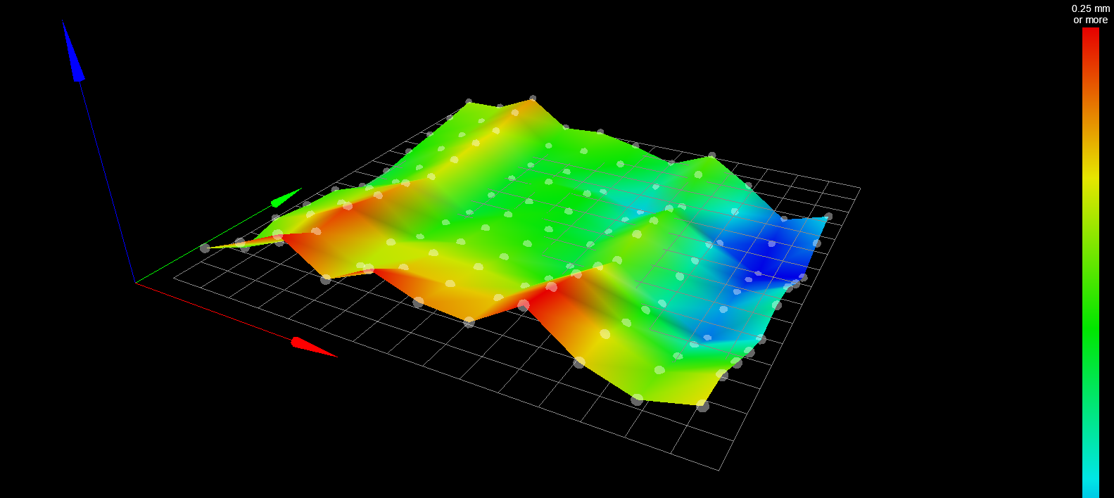
                  @re_tour thats only a guess though so it may be something else. maybe post a photo of your setup?

                  Owns various duet boards and is the main wiki maintainer for the Teamgloomy LPC/STM32 port of RRF. Assume I'm running whatever the latest beta/stable build is

                  re_tourundefined 1 Reply Last reply Reply Quote 0
                  • re_tourundefined
                    re_tour @jay_s_uk
                    last edited by

                    @jay_s_uk
                    280ffa87-e42d-49a6-beca-fae6576db9fe-kép.png

                    Creality Ender 3 | BIGTREETECH E3 RRF V1.1 Wifi | BLTouch | RepRap 3.3.0_11

                    jay_s_ukundefined 1 Reply Last reply Reply Quote 0
                    • jay_s_ukundefined
                      jay_s_uk @re_tour
                      last edited by

                      @re_tour do the peaks tie in with the diameter of the rollers?

                      Owns various duet boards and is the main wiki maintainer for the Teamgloomy LPC/STM32 port of RRF. Assume I'm running whatever the latest beta/stable build is

                      re_tourundefined 1 Reply Last reply Reply Quote 0
                      • re_tourundefined
                        re_tour @jay_s_uk
                        last edited by

                        @jay_s_uk Sorry, but what do you mean by that?

                        Creality Ender 3 | BIGTREETECH E3 RRF V1.1 Wifi | BLTouch | RepRap 3.3.0_11

                        jay_s_ukundefined 1 Reply Last reply Reply Quote 0
                        • jay_s_ukundefined
                          jay_s_uk @re_tour
                          last edited by

                          @re_tour whats the distance between the measuring points in X?

                          Owns various duet boards and is the main wiki maintainer for the Teamgloomy LPC/STM32 port of RRF. Assume I'm running whatever the latest beta/stable build is

                          re_tourundefined 3 Replies Last reply Reply Quote 0
                          • re_tourundefined
                            re_tour @jay_s_uk
                            last edited by

                            @jay_s_uk 15mm

                            Creality Ender 3 | BIGTREETECH E3 RRF V1.1 Wifi | BLTouch | RepRap 3.3.0_11

                            1 Reply Last reply Reply Quote 0
                            • re_tourundefined
                              re_tour @jay_s_uk
                              last edited by

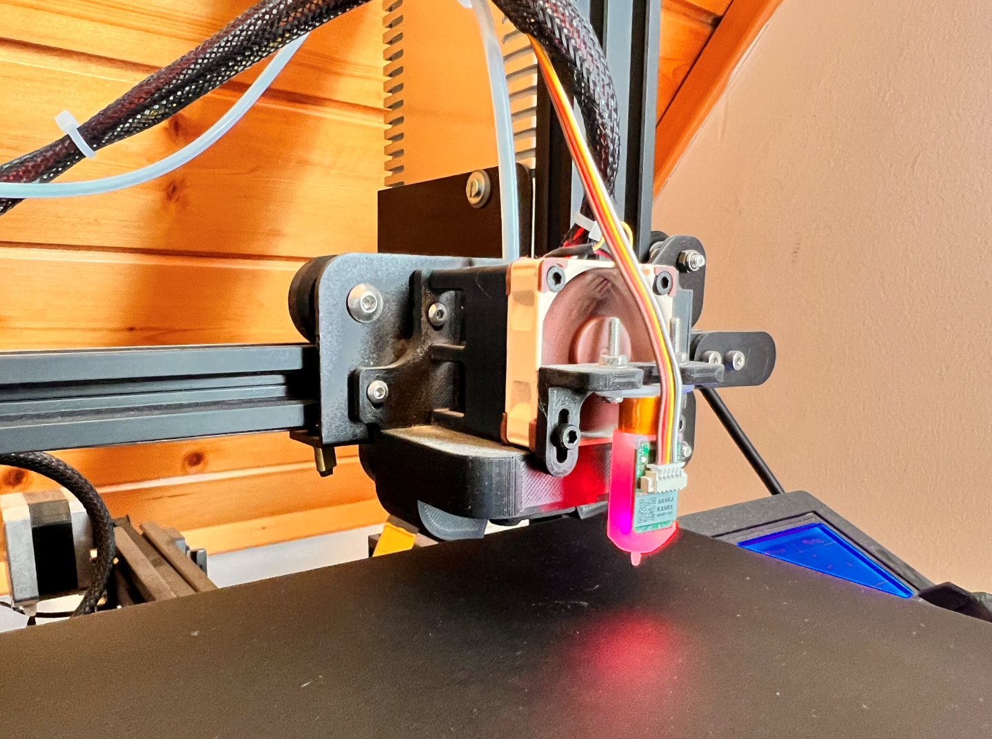
                              @jay_s_uk I did one more probing and now I have the same pattern with a bit different values

                              b1579dc3-cfbc-447e-a755-2d0873fa6b56-kép.png

                              Creality Ender 3 | BIGTREETECH E3 RRF V1.1 Wifi | BLTouch | RepRap 3.3.0_11

                              1 Reply Last reply Reply Quote 0
                              • re_tourundefined
                                re_tour @jay_s_uk
                                last edited by

                                @jay_s_uk The rollers are 44,5mm if you think of the ones that move the tool head on X

                                Creality Ender 3 | BIGTREETECH E3 RRF V1.1 Wifi | BLTouch | RepRap 3.3.0_11

                                jay_s_ukundefined 1 Reply Last reply Reply Quote 0
                                • jay_s_ukundefined
                                  jay_s_uk @re_tour
                                  last edited by

                                  @re_tour the rollers are 24mm. it may be linked to the quality of those. first off i would look at removing them and checking for crunchiness etc in their motion. You may be able to do that with the carriage mounted too.

                                  these are good if you need to replace any https://www.aliexpress.com/item/1005003495562376.html

                                  Owns various duet boards and is the main wiki maintainer for the Teamgloomy LPC/STM32 port of RRF. Assume I'm running whatever the latest beta/stable build is

                                  re_tourundefined 1 Reply Last reply Reply Quote 1
                                  • re_tourundefined
                                    re_tour @jay_s_uk
                                    last edited by

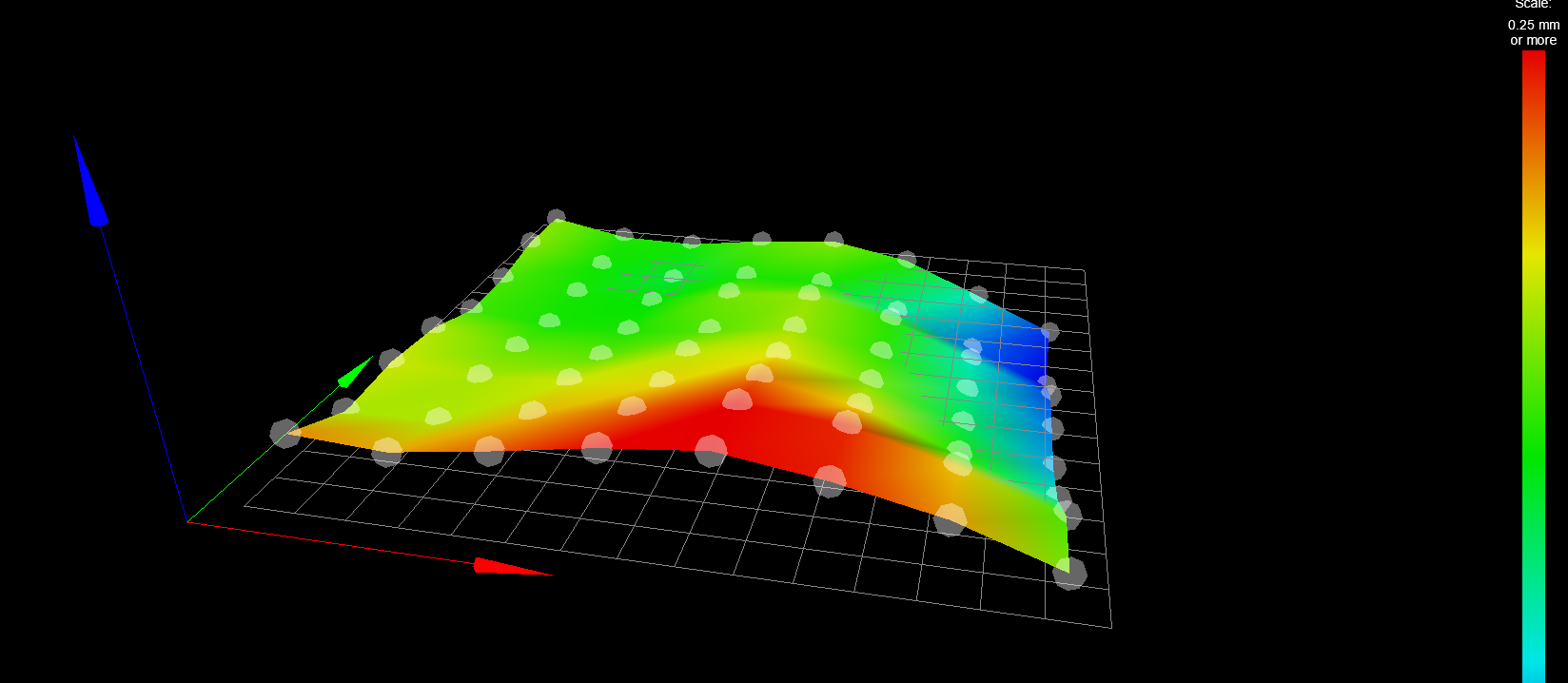
                                    @jay_s_uk well sh#t I guess I never even tought about the fact that debris can build up at the rollers...I did a mesh again, now it looks much better, however, there still is a bump which I dont really know how to correct?
                                    7269d4a2-7ae6-4c23-b75e-737ee43c5e3a-kép.png

                                    Creality Ender 3 | BIGTREETECH E3 RRF V1.1 Wifi | BLTouch | RepRap 3.3.0_11

                                    jay_s_ukundefined 1 Reply Last reply Reply Quote 0
                                    • jay_s_ukundefined
                                      jay_s_uk @re_tour
                                      last edited by

                                      @re_tour thats looking better.
                                      It could be a sagging or bent extrusion on X, although sagging seems unlikely

                                      Owns various duet boards and is the main wiki maintainer for the Teamgloomy LPC/STM32 port of RRF. Assume I'm running whatever the latest beta/stable build is

                                      re_tourundefined 2 Replies Last reply Reply Quote 0
                                      • re_tourundefined
                                        re_tour @jay_s_uk
                                        last edited by

                                        @jay_s_uk I have a magnetic pad on the bed, but I can't see any depressions or bumps...not visible ones at least, I just cleaned above and below the pads

                                        Creality Ender 3 | BIGTREETECH E3 RRF V1.1 Wifi | BLTouch | RepRap 3.3.0_11

                                        1 Reply Last reply Reply Quote 0
                                        • re_tourundefined
                                          re_tour @jay_s_uk
                                          last edited by re_tour

                                          @jay_s_uk Okay so, I cleaned the rollers, the mesh map looks better. I think the bumps should be compensated by the printer. However, now I cant for the love of god make the filament stay on the bed. I have it heated to 65C since the magnetic pad needs a bit higher temperature, but still the filament won't stick. I tried setting the Z offset to a smaller value, the problem is the same. I think the g-code my Cura puts out is also well configured:

                                          ; Ender 3 Custom Start G-code
                                          G92 E0 ; Reset Extruder
                                          G28 ; Home all axes
                                          G29 ; Does mesh probing
                                          G29 S1 ; Calls the mesh
                                          G1 Z2.0 F3000 ; Move Z Axis up little to prevent scratching of Heat Bed
                                          G1 X0.1 Y20 Z0.3 F5000.0 ; Move to start position
                                          G1 X0.1 Y200.0 Z0.3 F1500.0 E15 ; Draw the first line
                                          G1 X0.4 Y200.0 Z0.3 F5000.0 ; Move to side a little
                                          G1 X0.4 Y20 Z0.3 F1500.0 E30 ; Draw the second line
                                          G92 E0 ; Reset Extruder
                                          G1 Z2.0 F3000 ; Move Z Axis up little to prevent scratching of Heat Bed
                                          G1 X5 Y20 Z0.3 F5000.0 ; Move over to prevent blob squish
                                          

                                          This is the start code. Am I doing something wrong or its a trial end error thing where I have to find the sweet spot?

                                          Creality Ender 3 | BIGTREETECH E3 RRF V1.1 Wifi | BLTouch | RepRap 3.3.0_11

                                          infiniteloopundefined 1 Reply Last reply Reply Quote 0
                                          • infiniteloopundefined
                                            infiniteloop @re_tour
                                            last edited by

                                            @re_tour

                                            I think the bumps should be compensated by the printer.

                                            It is a common misconception to think of a height map as an image of the print bed’s surface - in fact, it represents the Z-sum of the deviations from the ideal in all mechanical parts. Looking at your latest map, the two bumps (in red and blue) possibly don’t represent deformations of your print bed.

                                            You should be able to verify these "bumps" with a ruler. If these are true deformations, use a mirror tile to flatten the surface. However, I think you should have a second look at your V-slot rollers (all axes). Especially the Y axis of the Ender (and the CR-10) is a common source of "joy" (and quite difficult to fix).

                                            Talking from experience, I know that the Creality printers are well able to lay down a first layer (0.2 mm) without using mesh compensation, just by fixing mechanical issues carefully. If you get that right, put the mesh on top to counter irregularities of the bed’s surface.

                                            re_tourundefined 1 Reply Last reply Reply Quote 2
                                            • First post
                                              Last post
                                            Unless otherwise noted, all forum content is licensed under CC-BY-SA