5 bar scara on duet3!
-
yep you've got it. It's a split ring design where one half matches the tooth count of the belt and the other half is +2 teeth. So for a 75t 3m HTD belt it's 75t on one half and 77t on the other. the input is the elliptical part (what @JoergS5 and I are going back and forth about bearings vs. full ellipse). The tolerance needs to be fairly tight to get zero backlash, but also needs to allow for the belt to "stretch" a tooth so the 77t side can precess +2 teeth forward. I just drew it up and it worked well on my first attempt so I guess it's not too tough to dial in?
Either of the two halves can be the output or fixed (that might be incorrect technically, but just from playing with it seems like that's true). Also remember for the belted design they're not involute gear teeth, but HTD pulley teeth.
-
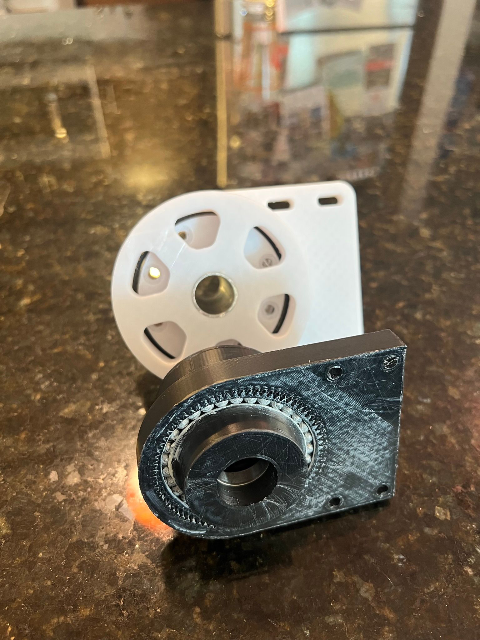
I threw together a design for a 35:1 harmonic drive that uses a standard harmonic design with an elliptical driver using ball bearings. getting the size and shape of the ellipse took a few iterations, but again wasn't too hard to sort out.
Once you pack grease into the ball bearings and the gear teeth the design runs a bit smoother and much quieter. I printed this one from ABS with a .25mm nozzle and it turned out great. It's a lot smaller diameter than the design with a belt in it. I made the cup on the flex spline taller to help improve flexibility. I need to design in the pulley to the elliptical driver. This one is just a solid round section so I could play with it.
I might just install each design, one on each arm and play around with them to see how they perform. I'm also finding that packing the bearings is going a bit better now that I've done it a few times. Its a bit more tedious, but might actually be faster than installing all the hardware that goes into the belt design. I like the simplicity of the fully printed flex spline a lot.

-
@michaelr123 great job, this looks fine!
If you're interested in lowering fraction or get higher torque, there is an additional idea to optimize the teeth, so more teeth are in contact. The following patents (all expired) addressed this topic, maybe you are interesting in them:
patent inventor Ishikawa:
EP0309197A2
US4823638A
US5918508A
US4974470Apatent inventor Aubin:
US5456139A
US5662008A
EP0640778A1
EP0767325B1inventor Grill:
EP0978667A2I found the Aubin most promising, but I have no decision yet.
Another idea is to use more teeth (200) and then they can be lower, so flexspline doesn't need to flex as much. Additionally, the commercial ones have flattended teeth a bit to ease getting the necessary distance (another advantage is that if there is abrasion, the teeth can "sink in" a bit and still are precise). The many balls of the wave generator gives good control over where it flexes.
-
@michaelr123 my previous post were additional ideas which may not be necessary for your use case. But I have another idea which may be relevant:
In my own constructions I tend to separate mechanical hinges from the actuator, i. e. in your case the hinges from the harmonic drive flexspline+circular spline+wave generator. The hinge is also important for precision, so an option would be to develop something like a cross roller bearing, or alternatively, two ball bearings with some distance to stabilize the axis.
-
This is a great resource! thank you for sharing. looking over these patents really quickly I think I've seen some of this in a research paper in a mechanical engineering journal: https://journals.sagepub.com/doi/full/10.1177/1687814019850656
I noticed with the 0.8m teeth you need a lot of motion for the strain wave to have enough displacement to move over to the next tooth. It looks like these patents and design paper have some equations on how much of an ellipse you need for a give tooth size and arrangement. I wonder how much of this would be captured in a plastic gear? It looks like I've got a well defined sketch for these squared off teeth to draw something and try it!
One reason I went with the size (tooth and diameter) was to have a more reasonable sized drive and a gear ratio that wasn't quite so high. I imagine tooth width and diameter again determines holding torque. I also imagine a higher tooth count will run smoother, my current design is only 74 - 72t.
For your other question, the new design uses pillow blocks for the 20mm steel shaft. So now I'm coupling and directly turning that rather than trying to couple to the arm component directly. I haven't posted a picture of the most current design!
-
@michaelr123 thanks for the link to the article, the idea looks familiar. I am using matlab to crosscheck some calculation results, it's a great program.
-
+1 for matlab too! I was convinced I was going to go to my corporate job after college and convince them to give up excel for matlab, I now use excel for everything lol.
although, I can get a student license again for only $100 through my MBA program...
-
This post is deleted! -
@michaelr123 said in 5 bar scara on duet3!:
student license aga
I bought the matlab with some toolboxes (Simulink, Vision, Image, Robotics). The Corke book (on his homepage) about robotics includes freeware toolboxes of vision and robotics (simpler versions of the matlab toolboxes) for matlab, because Corke developed the source of them.
-
A few more updates, I installed the original all printed flex spline as well as my updated design that uses a 0.6M tooth at 118t. It seems a lot smoother and higher precision which is heading in the right direction. The next thing I need to solve is connecting the flex spline to the 20mm steel rod. 6mm sets screws threaded into the plastic are not cutting it.
Here's a quick video showing how much flex I'm getting before the screws slip on the shaft:
https://youtube.com/shorts/vS0aS8M9vDY?feature=share
This magnifies quite a bit once it gets all the way out to the end effector with the second arm set attached. I think I need to sort out this flex before I can expect any sort of reasonable print quality. At the moment, if the arm bumps into the model being printed at all it's just going to get knocked out of the way.
I'm working on better way to secure the flex spline to the rod which I think will help some. Otherwise a couple of other ideas I had:
- Large diameter / larger tooth profile flex spline system without raising the gear ratio any higher.
- Stiffen the ring gear part, there does seem to be some flex in this part as it is.
- add a second driver to the arm to double the gearing contact the rod sees.
- shorten the arms a bit. Maybe I need to take a small step back on this first crack at a scara arm.
-
@michaelr123 I'm constantly working at the same questions like you: where does the flex come from and what to do against it. Your ideas are all valid and worth a try. My own ideas, which overlap with yours partly:
- calculate and decide where the flex comes from. Some possibilities:
- long arm length => high torque => more vibrating/flexing => against: shorter arm
- material of flex spline teeth flex => against: material mix flex spline outer to flex, teeth harder, connection to shaft harder. Teeth harder e.g. metal/epoxy or similar containing on top of teeth or in direction teeth-to-middle of shaft
- hinge where the harmonic drive is mounted on flexes => press hinge to one side with eg spring so it doesn't change position when direction changes (ball bearings are pressed to one side always)
- my preference so far is a doubled arm (vertical)
Plastic has an E-module of about 3 GPa, compared to aluminium of 70 and steel of 210. E-module is a number to calculate how much material bends under force, so choosing something harder may fix the flexing. Of course you want a flexspline to flex, so the teeth shall be hard and the inner ring flexible. There are thermosplasts to be 3d printed and hard at the same time, this would be an option, besides using alu/steel. My own path is the (spring-)steel way.
Some of the commercial harmonic drives have about 200 teeth, and this a number which pleases me, because one can produce them easy with 200-step steppers. But this will not solve the flexing, only make it more precise.
I can't remember whether I have already written it, I tend to separate hinge mechanical construction from the actuator part:
- hinge, arm as stable as possible
- actuatator, teeth as precise as possible
This separate handling makes analyzing where flex comes from easier.
In your case, I suspend the flex of the teeth and/or flex of the big ring (= the flexspline part which is between teeth and shaft). Maybe it helps to make it stronger (=thicker and reinfoces by eg spring steel) to flex less.A final thought: it always help me to imagine that I am a part of the mechanism and how do I act/react: when there is force to the arm, where does the force go? Here it goes to the circular-spline versus flexspline teeth ("horizontal" in respect to teeth, to the flanks of the teeth), so how to enforce it and remove play? Maybe there is teeth-teeth play also, then there needs to be more force from flexpline in direction of circular spline (vertical to shaft in direction outer). More engaged teeth (as described in the patents) will help as well. Another possibility is to make the teeth steeper (but not too steep, as they need to meet them), because steeper meens to have more force and precision. You can start mixing steep with less steep (steep for force and precision, less steep to make sure the teeth meeth each other. One tooth off would be a desaster for precision*)).
*) when mixing, be aware to jump the right amount after each round into the same kind of teeth (eg 200-204 and two kinds of teeth, this should work).
-
final thought:
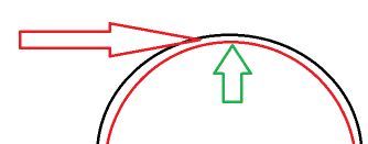
I find harmonic drives fascinating because of the following idea in the image:
- green is the force of the wave generator pressing the flexspline teeth against the circular spline teeth. This defines the position of the teeth and is with low pressure. It also hinders position change with low force (detent torque of stepper may be enough as brake).
- red arrow is the force of your arm sideways to the flanks of the teeth
The different direction of the forces allow to optimize them separately. Your current problem is with the red arrow. but maybe the green one has not pressed the teeth enough.
-
All great points. First I need to develop a clamp that fixes the output to the shaft. From there I can figure out where the flex is coming from. I can take another crack or two at improving this aspect of the machine, but I may just need to get it actually up and running to see where I'm at. I may also need to humble myself a bit and scale down the arm depending on how testing goes. I think this is the best iteration from a stiffness and resolution standpoint.
I could switch from ABS to PLA on the ring gear to have a stiffer material there to your point. I'll also shrink the height of the flex spline as I don't think it's necesary to have so much length there with plastic. I also would like to mount the ring gear directly to the 80/20 extrusion while also further increasing the diameter. I'll need to reconfigure the motor mount a bit, but all those changes should help. Maybe I'll try making a huge harmonic drive just to see how it performs under the sort of torque. 200t at a .8M gear tooth or something like that.
Another idea I had was to just print the spline without the cup at the bottom. Then I could use a steel hose clamp to fix the the flex spline tightly to a set block that can grab onto the 20mm shaft. I'll draw up a picture here to explain, but it would also help reduce the amount of printing that requires a .25mm nozzle to help speed up prototyping.
-
@michaelr123 said in 5 bar scara on duet3!:
print the spline without the cup at the bottom
The advantage is that you can replace the teeth-part fast when it is worn out, if you find a good connector between the two parts. And exchange ratios fast.
PLA is even lower e-module than ABS. PLA has between 1 and 3 GPa, ABS has 2.3 GPa. I would recommend to make it thicker, but use a flexible material like PP (polypropylen). Thermoplast, but very difficult to glue. An example application is Hylite (see Zatsit).
-
I am not sure what the reason is for the flexibility, but I hope you find it out. I'm sure the commecial producers are using finite element methods to find out the best balance between stability and flexibility.
-
Hello!
More changes and another update. I played around with a few more harmonic drive designs, and found they all had more backlash at the end effector than what I wanted. I had better luck with gear drives, and I also have found an appreciation for the back-drivability. So I scrapped the old design, developed a 45:1 gear drive design and rebuilt it one more time. I now think I have something workable at this point!
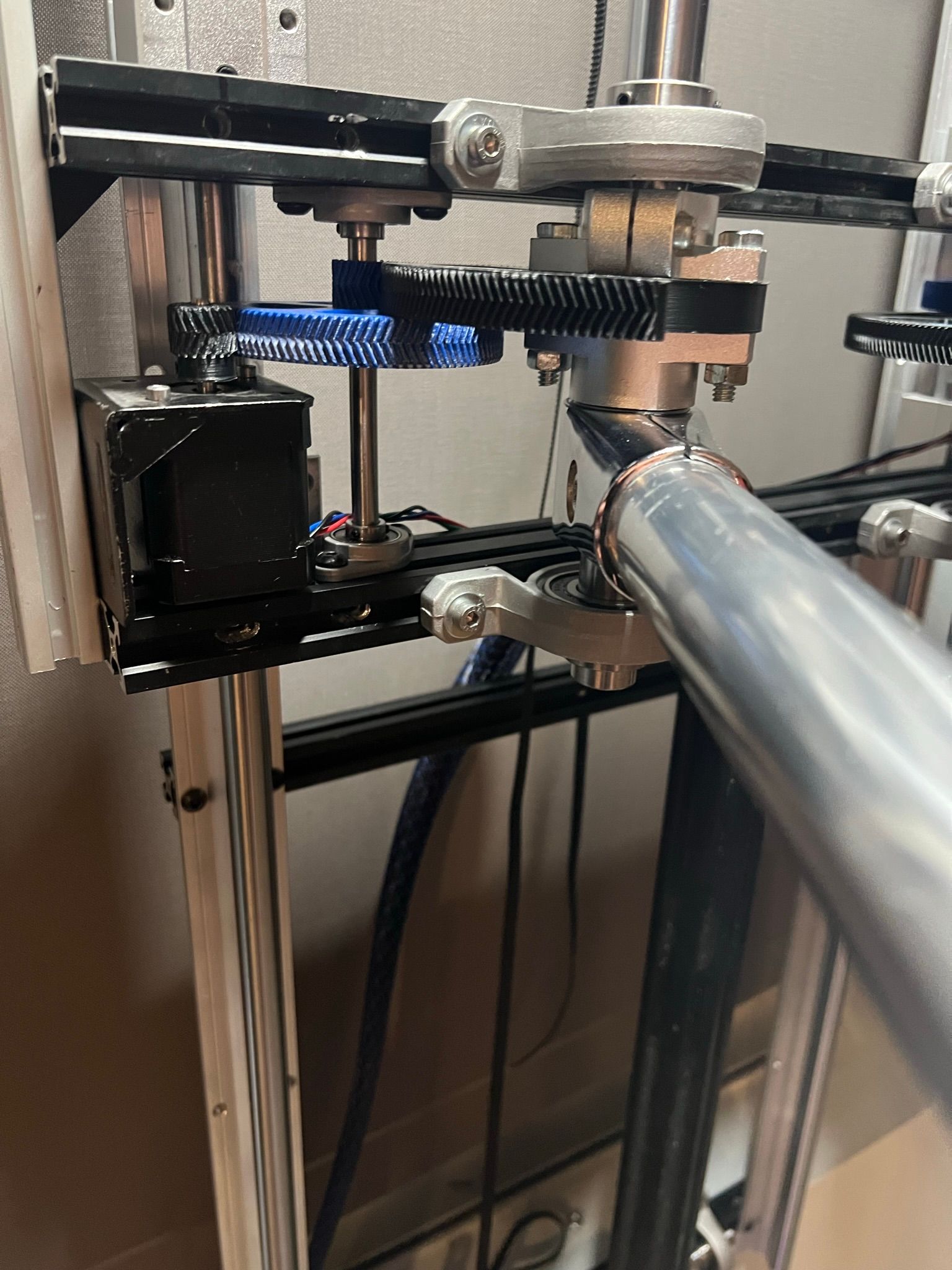
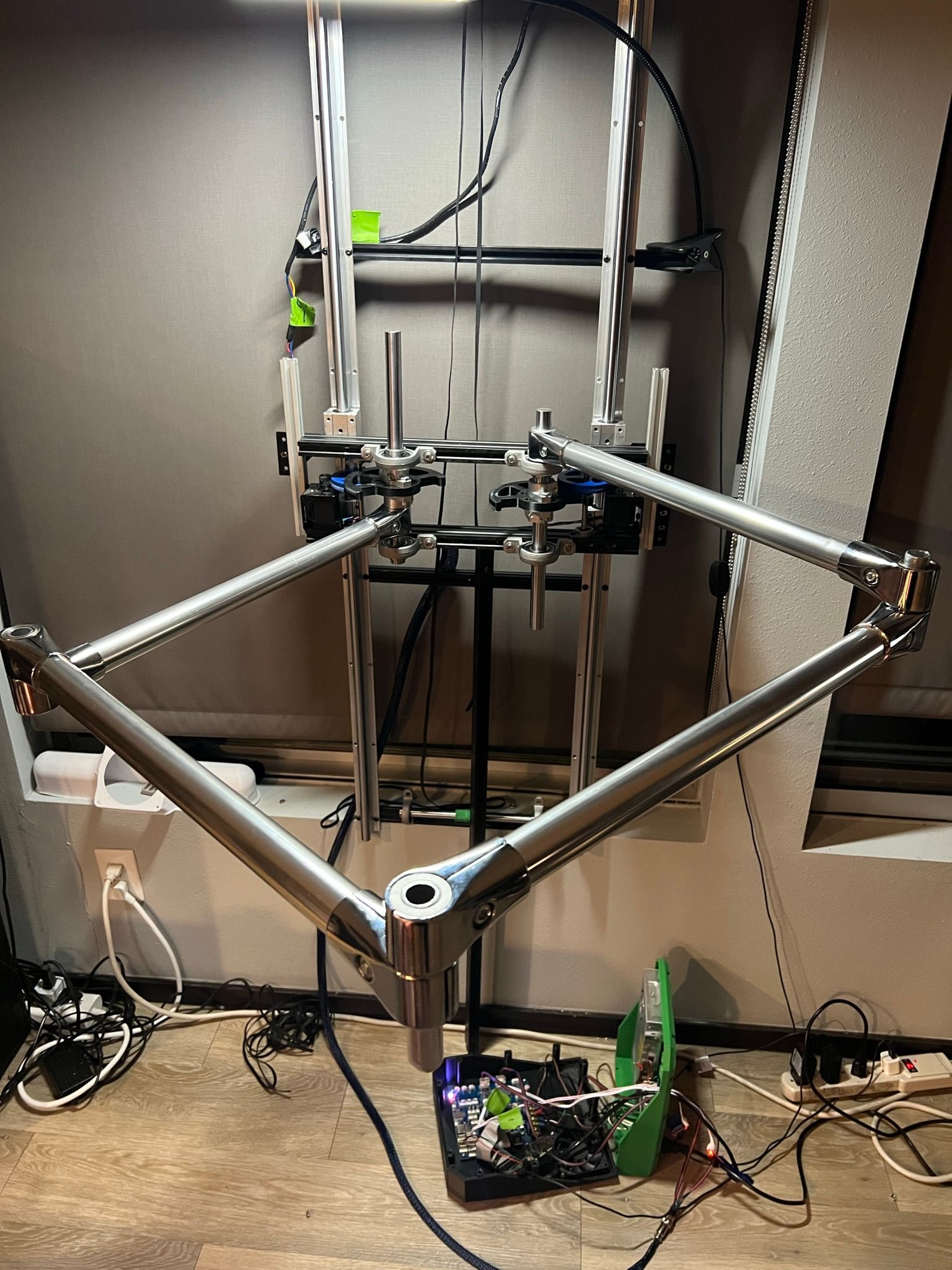
https://youtube.com/shorts/Yw_aW_2YJ5AAs you can see in the video, the system runs very smooth.
this is still running with just manual move codes, but now that I've got an XY motion system I'm going to start rebuilding the electronics to start working on calibration! List of things to knock out:
- Get endstops and other electrical bits cabled and installed
- Calibrate XY motion system
- Finish Z axis
- install extruder system and get a toolboard working
- get the build plate setup
- print something!
-
@michaelr123 congratulations, this looks like a very stable and reliable solution at the stepper+gear side! Please go ahead for a good printer!
-
@michaelr123 I'll proceed with building robot prototypes soon, using harmonic drives. It would be nice if you could give a short summary which problems you had to DIY them, especially why you had backlash.
-
Yeah I'd be happy to! I'll throw together a little YouTube video going over each design for you.
I think it comes down to how tight you make the fit and the ratio between the long and short sides of the elliptical driver. There's more work to do with that I think. You need to be careful with how much torque is then required to drive the elliptical driver. Depending on the application, the ones I have would probably be fine, but with a 28" lever arm it was just too much backlash or flex. I just don't want that to add more error when I start calibrating the xy system.
What kind of robot are you building? I'd be interested to see what you're working on.
-
@michaelr123 said in 5 bar scara on duet3!:
What kind of robot are you building? I'd be interested to see what you're working on.
I started about three years ago with 5-bar-scara and developed the kinematics for it for RRF. Since then I'm developing robot kinematics, which includes all sorts of combinations of rotary and linear axes. So I'm building 6 axis industrial robots, but also CNC 5 axis and Cartesian ones. With extensions, the robot kinematics can support parallel kinematics also, like 5-bar-scara, CoreXY 5 axis and tripteron.
The project thread is https://forum.duet3d.com/topic/17421/robotic-kinematics/330?_=1670950282842 and https://forum.duet3d.com/topic/30228/robot-prototypes-robot-kinematics (but there are other pages about prototypes, because I made several tries) and documentation at https://docs.duet3d.com/User_manual/Machine_configuration/Configuring_RepRapFirmware_for_a_Robot_printer with multiple linked pages.
I've started with what I read about robots, the Siciliano book, based on Denavit-Hartenberg, but discovered a half year ago that screw theory is superior. Then I detected geometric algebra as method to solve some unsolved problems, and this is the status today. I rewrite the kinematics to the new methods and start prototyping after it.
An open question is Stewart-Gough. I'm not sure whether I can manage to develop it. And one interesting topic is to support compliant hinges. (I mean e. g. the book Howell Handbook of Compliant Mechanisms).